Download
1 / 32
640 likes | 2.52k Vues
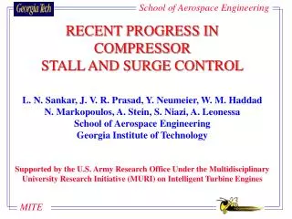
RECENT PROGRESS IN COMPRESSOR STALL AND SURGE CONTROL. L. N. Sankar, J. V. R. Prasad, Y. Neumeier, W. M. Haddad N. Markopoulos, A. Stein, S. Niazi, A. Leonessa School of Aerospace Engineering Georgia Institute of Technology

E N D
RECENT PROGRESS IN COMPRESSOR STALL AND SURGE CONTROL L. N. Sankar, J. V. R. Prasad, Y. Neumeier, W. M. Haddad N. Markopoulos, A. Stein, S. Niazi, A. Leonessa School of Aerospace Engineering Georgia Institute of Technology Supported by the U.S. Army Research Office Under the Multidisciplinary University Research Initiative (MURI) on Intelligent Turbine Engines
Modern turbine engines are highly developed, complex systems. There is a continuing trend towards fewer stages, and high pressure ratios per compression stage. Compressor instabilities (rotating stall and surge) develop, that must be controlled at high pressure ratios, especially at low mass flow rates. Background
Desired Extension of Operating Range Lines of Constant Efficiency Lines of Constant Rotational Speed Surge Limit Total Pressure Rise Choke Limit Volumetric Flow Rate Compressor Performance Map
Peak Performance Mean Operating Point Pressure Rise Limit Cycle Oscillations Pressure Rise Flow Rate Flow Rate Surge Mild Surge Deep Surge An “axisymmetric” phenomenon that causes periodic variations in mass flow rate and pressure rise. Deep surge can create a reversed flow in the entire compression system.
1 Local Separation Local Separation ROTATING STALL Rotating Stall is a local separation pattern that rotates at a fraction of the spool RPM
Bleed Air Controller Unit Pressure Sensors Air Injection Different Strategies for Compressor Control Guide Vanes Bleed Valves Steady Blowing Movable Plenum Walls
An excellent survey by Bram de Jager summarizes worldwide activities on rotating stall and surge control. A number of researchers in U. S. are exploring compressor stall and surge control, using theoretical, computational, and experimental techniques. MIT, Purdue, Penn State, Cal Tech, Wright Labs, and all major U. S. Industries This presentation will focus on Georgia Tech Activities. Prior Work
Georgia Tech Center for Intelligent Turbine Engines Start Date: November 1, 1995 Research Team: Eleven faculty members with expertise in controls, compressors, combustion, propulsion, fluid mechanics, diagnostics, MEMS and neural net. Facilities: Combustion, compressor, micro- electronics and fluid mechanics laboratories Research Areas: Control of combustor processes, Nonlinear control theory, Control of compressor stall and surge, MEMS
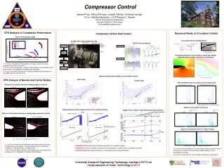
Two and three-dimensional compressible flow solvers for modeling compressor stall and surge control Multi-mode models for rotating stall and surgein axial flow compressors Centrifugal compressor model for surge control involving pressure, mass flow rate, and impeller RPM dynamics Model extensions for compressor stall control via fuel modulations Compressor Control- Modeling Efforts
Reduced order models based on CFD for modelingcompression system transients Optimal nonlinear control framework to address disturbance rejection, control saturation and robustness Adaptive control framework for elimination of rotating stall and surge Nonlinear stabilization framework for interactionbetween higher order system modes Combined model and fuzzy rule based methodologyto address actuator rate and amplitude limits Corrections to rotating stall control theories. Compressor Control- Theory
Experimental Studies • Experimental Demonstrations • Rotating stall control through • Throttling • Recirculation of air from plenum to inlet • Combustion process modulations • Passive means • New facility development • A centrifugal compressor facility for the study of flow dynamics, and for the development of active and passive control methods
Experimental Studies Control Theory CFD Modeling Sample Results
Schematic of the Axial Compressor Facility (Fuel Control) Diffusion flame simulates heat release in a real engine combustor Operating point around 300 0F
Fuzzy Rules were developed using numerical simulations. The numerical simulations utilized the Moore-Greitzer Model, a system of ODEs. Control variable was the amount of opening of a bleed valve placed in the plenum chamber. Following simulations, these rules were implemented in hardware, at our axial compressor facility. Fuzzy Logic Control of Rotating Stall
Fuzzy Logic Controller Measured/Computed Pressure Fluctuations at compressor casing Throttle Opening Output Compression System Inference Engine Defuzzifier Fuzzifier
Fuzzy Logic Control of Rotating Stall 800000 700000 Closed-Loop Fuzzy Logic Control 50% Bleed 600000 500000 Rotating Stall Amplitude 50% bleed 100% 400000 300000 No bleed 200000 100000 0 0 10 20 30 40 50 60 70 80 90 100 Main Throttle(%)
CFD Modeling • Detailed study and simulation of NASA Low Speed Centrifugal Compressor • Simulation and Validation of Air Bleeding & Blowing/Injection as a Means to Control and Stabilize Compressors Near Surge Line • Useful Operating Range of Compressor was Extended to 60% Below Design Conditions
Simulation Setup NASA Low Speed Centrifugal Compressor • 20 Full Blades with 55° Backsweep • Inlet Diameter 0.87 m • Exit Diameter 1.52 m • Tip Clearance 2.54 mm (1.8% of Blade Height ) • Design Conditions: • Mass Flow Rate 30 kg/sec • Rotational Speed 1862 RPM • Total Pressure Ratio 1.14 • Adiabatic Efficiency 0.992
C Uncontrolled Operation Uncontrolled, Stall Operation Large, Unbounded Fluctuations
Off-Design Results (Uncontrolled) Velocity Vectors at Midpassage TE Growing Reversed Flow Unstable Condition Blades Stall After 3 Cycles (t*) At Beginning LE After 1 Cycle After 3 Cycles (t*)
Casing 0.04RInlet a = 5° Impeller RInlet Rotation Axis Compressor Control Setup Injection Angle, =5º Yaw Angle, =0º 5% or 10% Injected Mass Flow Rate
D . m=17.5 kg/sec ) Controlled Operation Controlled Operation with 10% Air Injection ( Fluctuations are Decreased to 2~3% Extension of Useful Operating Range (60% Below Design)
Air Injection Injected Air (10%) Controlled, Stable Operation Injection Suppresses Stalled Reverse Flow Regions Near LE
DLR Centrifugal Compressor Control simulations are currently in progress
51.4 cm NASA ROTOR-67Axial Compressor Relative Mach No. at 30% Pitch 1.6 CFD 1.4 EXP.l 1.2 M 1 0.8 0.6 -125 -50 25 100 175 250 % Chord Results for Rotating Stall Simulation considering six flow passages are in progress
A concerted effort involving control theory, simulations and experimental studies is underway at Georgia Tech to understand and control compressor instabilities. Encouraging results have been obtained in all these areas. A combined CFD-Feedback Control simulation is currently in progress. Concluding Remarks