Download
1 / 67
670 likes | 804 Vues
This research explores innovative architectures for billion transistor chips, focusing on multicore systems. We address performance scaling by implementing a Scheduled Dataflow (SDF) model that decouples memory access from execution, allowing for efficient non-blocking multithreading. Energy management is crucial for embedded systems, and our proposed designs leverage intelligent memory management (IRAM) and specialized cache systems to minimize redundancy, enhance performance, and maintain power efficiency. Our findings show significant advantages in reducing energy consumption while optimizing processing capabilities.

E N D
Billion Transistor Chips Multicore Low Power Architectures Krishna Kavi Department of Computer Science and Engineering The University of North Texas kavi@cse.unt.edu http://csrl.unt.edu/~kavi Computer Systems Research at UNT
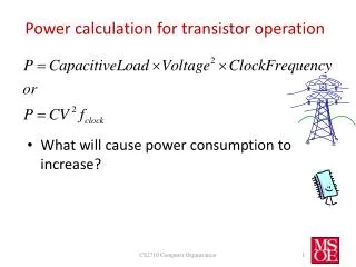
More CPU’s per chip -- Multi-core systemsMore threads per core -- hyper-threadingMore cache and cache levels (L1, L2, L3)System on a chip and Network on chipHybrid system including reconfigurable logic Billion Transistor Chips How to garner the silicon real-estate for improved performance? But, embedded system require careful management of energy Computer Systems Research at UNT
We propose innovative architecture that “scales” in performance as needed, but disables hardware elements when not needed.We address several processor elements for performance and energy savings Billion Transistor Chips How to garner the silicon real-estate for improved performance? Multithreaded CPUs Cache Memories Redundant function elimination Offload administrative functions Computer Systems Research at UNT
Computer Architecture Research A new multithreaded architecture called Scheduled Dataflow(SDF) Uses Non-Blocking Multithreaded Model Decouples Memory access from execution pipelines Uses in-order execution model (less hardware complexity) The simpler hardware of SDF may lend itself better for embedded applications with stringent power requirements Computer Systems Research at UNT
Computer Architecture Research Intelligent Memory Devices (IRAM) Delegate all memory management functions to a separate processing unit embedded inside DRAM chips More efficient hardware implementations of memory management are possible Less cache conflicts between application processing and memory management More innovations are possible Computer Systems Research at UNT
Computer Architecture Research Array and Scalar Cache memories Most processing systems have a data cache and instruction cache. WHY? Can we split data cache into a cache for scalar data and one for arrays? We show significant performance gains with 4K scalar cache and 1k array cache we get the same performance as a 16K cache Computer Systems Research at UNT
Computer Architecture Research Function Reuse Consider a simple example of a recursive function like Fib int fib (int); int main() { printf ("The value is %d .\n ", fib (num) )} int fib (int num) { if (num == 1) return 1; if (num == 2) return 1; else {return fib (num-1) + fib (num-2);} For Fib (n), we call Fib(n-1) and Fib(n-2); For Fib(n-1) we call Fib(n-2) and Fib (n-3) So we are calling Fib(n-2) twice Can we somehow eliminate such redundant calls? Computer Systems Research at UNT
Computer Architecture Research What we propose is to build a table in hardware and save function Calls. Keep the “name”, and the input values and results of functions When a function is called, check this table if the same function is called with the same inputs If so, skip the function call, and use the result from a previous call Computer Systems Research at UNT
This slide is deliberately left blank Computer Systems Research at UNT
Overview of our multithreaded SDF Based on our past work with Dataflow and Functional Architectures Non-Blocking Multithreaded Architecture Contains multiple functional units like superscalar and other multithreaded systems Contains multiple register contexts like other multithreaded systems Decoupled Access - Execute Architecture Completely separates memory accesses from execution pipeline Computer Systems Research at UNT
Background • How does a program run on a computer? • A program is translated into machine (or assembly) language • The program instructions and data are stored in memory (DRAM) • The program is then executed by ‘fetching’ one instruction at a time • The instruction to be fetched is controlled by a special pointer called program counter • If an instruction is a branch or jump, the program counter is changed to the address of the target of the branch Computer Systems Research at UNT
Dataflow Model • Pure Dataflow Instructions • 1: LOAD 3L / load A, send to Instruction 3 • 2: LOAD 3R / load B, send to Instruction 3 • 3: ADD 8R, 9R / A+B, send to Instructions 8 and 9 • 4: LOAD 6L, 7L / load X, send to Instructions 6 and 7 • 5: LOAD 6R, 7R / load Y, send to Instructions 6 and 7 • 6: ADD 8L / X+Y, send to Instructions 8 • 7: SUB 9L / X-Y, send to Instruction 9 • 8: MULT 10L / (X+Y)*(A+B), send to Instruction 10 • 9: DIV 11L / (X-Y)/(A+B), send to Instruction 11 • 10: STORE / store first result • 11: STORE / store second result • MIPS like instructions • 1. LOAD R2, A / load A into R2 • 2. LOAD R3, B / load B into R3 • 3. ADD R11, R2, R3 / R11 = A+B • 4. LOAD R4, X / load X into R4 • 5. LOAD R5, Y / load Y into R5 • 6. ADD R10, R4, R5 / R10 = X+Y • 7. SUB R12, R4, R5 / R12 = X-Y • 8. MULT R14, R10, R11 / R14 = (X+Y)*(A+B) • 9. DIV R15, R12, R11 / R15 = (X-Y)/(A+B) • 10. STORE ...., R14 / store first result • 11. STORE ....., R15 / store second result Computer Systems Research at UNT
SDF Dataflow Model We use dataflow model at thread level Instructions within a thread are executed sequentially We also call this non-blocking thread model Computer Systems Research at UNT
Blocking vs Non-Blocking Thread Models • Traditional multithreaded systems use blocking models • A thread is blocked (or preempted) • A blocked thread is switched out • and execution resumes in future • In some cases, the resources of a blocked thread • (including register context) may be assigned to other • awaiting threads. • Blocking models require more context switches • In a non-blocking model, once a thread begins execution, it • will not be stopped (or preempted) before it • completes execution Computer Systems Research at UNT
Non-Blocking Threads Most functional and dataflow systems use non-blocking threads A thread/code block is enabled when all its inputs are available. A scheduled thread will run to completion. Similar to Cilk Programming model Note that recent versions of Cilk (Clik-5) permits thread blocking and preemptions Computer Systems Research at UNT
Cilk Programming Example • thread fib (cont int k, int n) • { if (n<2) • send_argument (k, n) • else{ • cont int x, y; • spawn_next sum (k, ?x, ?y); /* create a successor thread • spawn fib (x, n-1); /* fork a child thread • spawn fib (y, n-2); /* fork a child thread • }} • thread sum (cont int k, int x, int y) • {send_argument (k, x+y);} /* return results to parent’s /*successor Computer Systems Research at UNT
sum Join counter 2 cont x y fib 0 c o cont d n-1 e fib 0 cont n-2 Cilk Programming Example Computer Systems Research at UNT
Decoupled ArchitecturesSeparate memory accesses from execution Separate Processor to handle all memory accesses The earliest suggestion by J.E. Smith -- DAE architecture Computer Systems Research at UNT
Limitations of DAE Architecture • Designed for STRETCH system with no pipelines • Single instruction stream • Instructions for Execute processor must be coordinated with the data accesses performed by Access processor • Very tight synchronization needed • Coordinating conditional branches complicates the design • Generation of coordinated instruction streams for Execute and Access my prevent traditional compiler optimizations Computer Systems Research at UNT
Our Decoupled Architecture We use multithreading along with decoupling ideas Group all LOAD instructions together at the head of a thread Pre-load thread’s data into registers before scheduling for execution During execution the thread does not access memory Group all STORE instructions together at the tail of the thread Post-store thread results into memory after thread completes execution Data may be stored in awaiting Frames Our non-blocking and fine grained threads facilitates a clean separation of memory accesses into Pre-load and Post-store Computer Systems Research at UNT
Pre-Load and Post-Store • LD F0, 0(R1) LD F0, 0(R1) • LD F6, -8(R1) LD F6, -8(R1) • MULTD F0, F0, F2 LD F4, 0(R2) • MULTD F6, F6, F2 LD F8, -8(R2) • LD F4, 0(R2) MULTD F0, F0, F2 • LD F8, -8(R2) MULTD F6, F6, F2 • ADDD F0, F0, F4 SUBI R2, R2, 16 • ADDD F6, F6, F8 SUBI R1, R1, 16 • SUBI R2, R2, 16 ADDD F0, F0, F4 • SUBI R1, R1, 16 ADDD F6, F6, F8 • SD 8(R2), F0 SD 8(R2), F0 • BNEZ R1, LOOP SD 0(R2), F6 • SD 0(R2), F6 • Conventional New Architecture Computer Systems Research at UNT
Features Of Our Decoupled System • No pipeline bubbles due to cache misses • Overlapped execution of threads • Opportunities for better data placement and prefetching • Fine-grained threads -- A limitation? • Multiple hardware contexts add to hardware complexity If 36% of instructions are memory access instructions, PL/PS can achieve 36% increase in performance with sufficient thread parallelism and completely mask memory access delays! Computer Systems Research at UNT
Pre-Load • LOAD RFP| 2, R2 / load A into R2 • LOAD RFP| 3, R3 / load B into R3 • LOAD RFP| 4, R4 / load X into R4 • LOAD RFP| 5, R5 / load Y into R5 • LOAD RFP| 6, R6 / frame pointer for returning first result • LOAD RFP| 7, R7/ frame offset for returning first result • LOAD RFP| 8, R8 / frame pointer for returning second result • LOAD RFP| 9, R9/ frame offset for returning second result • Execute • ADD RR2, R11, R13 / compute A+B, Result in R11 and R13 • ADD RR4, R10 / compute X+Y, Result in R10 • SUB RR4, R12 / compute X – Y, Result in R12 • MULT RR10, R14 / compute (X+Y)*(A+B), Result in R14 • DIV RR12, R15 / compute (X-Y)/(A+B), Result in R15 • Post-Store • STORE R14, R6|R7 / store first result • STORE R15, R8|R9 / store second result A Programming Example Computer Systems Research at UNT
A Programming Example Computer Systems Research at UNT
Conditional Statements in SDF • Pre-Load • LOAD RFP| 2, R2 / load X into R2 • LOAD RFP| 3, R3 / load Y into R3 • / frame pointers for returning results • / frame offsets for returning results • Execute • EQ RR2, R4 / compare R2 and R3, Result in R4 • NOT R4, R5 / Complement of R4 in R5 • FALLOC “Then_Thread” / Create Then Thread (Allocate Frame memory, Set Synch-Count, • FALLOC “Else_Thread” / Create Else Thread (Allocate Frame memory, Set Synch-Count, • FORKSP R4, “Then_Store” /If X=Y, get ready post-store “Then_Thread” • FORKSP R5, “Else_Store” /Else, get ready pre-store “Else_Thread” • STOP • In Then_Thread, We de-allocate (FFREE) the Else_Thread • and vice-versa Computer Systems Research at UNT
SDF Architecture Execute Processor (EP) Memory Access Pipeline Synchronization Processor (SP) Computer Systems Research at UNT
Preload Execute Poststore Execute Poststore Execute Poststore Execute Preload Execute Execution of SDF Programs Preload Thread 1 Preload Preload Thread0 Thread 4 Poststore Thread 2 SP =PL/PS EP=EX Thread 3 Poststore Computer Systems Research at UNT
Scalability of SDF (Matrix) Scalability of SDF (FFT) In Order Out of Order SDF In Order Out of Order SDF 60000000 50000000 4000000 40000000 3000000 30000000 2000000 Execution Cycles Cycles Execution 20000000 1000000 10000000 0 0 2+1 2+2 3+2 3+3 4+3 4+4 5+4 5+5 2+1 2+2 3+2 3+3 4+3 4+4 5+4 5+5 Number of Functional Units Number of Functional Units Scalability of SDF (Zoom) In Order Out of Order SDF 6000000 4000000 Cycles Execution 2000000 0 2+1 2+2 3+2 3+3 4+3 4+4 5+4 5+5 6+5 6+6 Number of Functional Units Some Performance Results Computer Systems Research at UNT
Some Performance ResultsSDF vs Supersclar and VLIW Computer Systems Research at UNT
Some Performance ResultsSDF vs SMT Computer Systems Research at UNT
Some Scalability Data Computer Systems Research at UNT
Speculative Thread Execution Architecture Model Computer Systems Research at UNT
Speculative Thread Execution We extend MESI cache coherency protocol Our states are: Computer Systems Research at UNT
Speculative Thread Execution • Transition Diagram (processor) Computer Systems Research at UNT
Speculative Thread Execution • Transition Diagram (bus) Computer Systems Research at UNT
Speculative Thread Execution • Node structure Computer Systems Research at UNT
Speculative Thread Execution • Synthetic Benchmark Result Computer Systems Research at UNT
Speculative Thread Execution • Real Benchmarks Computer Systems Research at UNT
This slide is deliberately left blank Computer Systems Research at UNT
Array and Scalar Caches Two types of localities exhibited by programs Temporal: an item accessed now may be accessed in the near future Spatial: If an item is accessed now, nearby items are likely to be accessed in the near future Instructions and Array data exhibit spatial Scalar data items (such as loop index variable) exhibit temporal So, we should try to design different types of caches for arrays and scalar data Computer Systems Research at UNT
Array and Scalar Caches Comparing Split and Unified Cache Unified CacheDirect mappedBlock size: 32 bytesSplit Cachescalar cache: 2-way set associative 32 bytes blocksarray cache: Direct mapped 128 byte blocks Computer Systems Research at UNT
Summary of Results with array and scalar caches using SPEC 2000 Benchmarks Array and Scalar Caches • 43% reduction in Miss rate for benchmark art and mesa • 24% reduction in Miss rate for benchmark equake • 12% reduction in Miss rate for benchmark ammp Computer Systems Research at UNT
Augmenting scalar cache with victim cache and array cache with prefetch buffers Array and Scalar Caches What is a Victim Cache? A small fully associative cache to augment L1 direct mapped cache On a cache miss, the displaced cache entry is moved to victim cache Minimizes the number of conflict misses Computer Systems Research at UNT
Array and Scalar Caches Results Conventional cache configuration: 16k, 32 bytes block, Direct mapped Scalar cache configuration: 4k, 64 bytes block, Direct mapped with 8 lined Victim cache Array cache configuration: 4k, 64 bytes block, Direct mapped with multiple (4) 10 lined stream buffers Computer Systems Research at UNT
Embedded applications Array and Scalar Caches Tighter constraints on both functionality and implementation. Must meet strict timing constraints Must be designed to function within limited resources such as memory size, available power, and allowable weight Split caches can address these challenges Computer Systems Research at UNT
Array and Scalar Caches Reconfigurability • The performance of a given cache architecture is largely determined by the behavior of the applications • Manufacturer typically sets the cache architecture as a compromise across several applications • This leads to conflicts in deciding on total cache size, line size and associativity • For embedded systems where everything needs to be cost effective, this “one-size-fits-all” design philosophy is not adequate Computer Systems Research at UNT
Array and Scalar Caches Reconfigurability • Our goal is to design caches that achieve high performance for embedded applications while remaining both energy and area efficient • We apply reconfigurability to the design of caches to address these conflicting requirements • Emphasize only on cache size • We did not implement reconfigurability for associativity as cache splitting and victim caching solves that problem Computer Systems Research at UNT
Benchmarks Array and Scalar Caches Computer Systems Research at UNT
Array and Scalar Caches Percentage reduction of power, area and cycle for instruction cache Conventional cache configuration: 8k, Direct mapped instruction cache, 32k 4-way Unified level 2 cache Our Instruction cache configuration: Size variable, Direct mapped with variable sized prefetch buffer Computer Systems Research at UNT
Array and Scalar Caches Percentage reduction of power, area and cycle for data cache Conventional cache configuration: 8k, Direct mapped data cache, 32k 4-way Unified level 2 cache Scalar cache configuration: Size variable, Direct mapped with 2 lined Victim cache Array cache configuration: Size variable, Direct mapped Computer Systems Research at UNT