Download
1 / 18
230 likes | 312 Vues
Dive into the world of Digital IC technology with Professor Dr. M. N. Tibdewal as he discusses the characteristics and advancements in this field. Learn about logic families, power dissipation, noise immunity, and more.

E N D
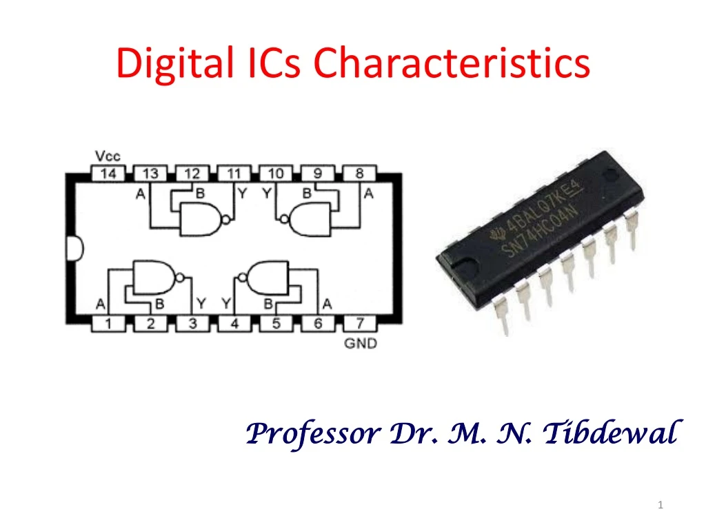
Digital ICs Characteristics Professor Dr. M. N. Tibdewal
Digital ICs • Digital IC technology has advanced rapidly changing integrations, which can fabricate million or more gates. • ICs pack more circuitry in a small package, so overall size of almost any system is reduced.
Digital ICs ICs have made digital systems more reliable by reducing the number of external interconnections from one device to another. Protected from poor soldering, breaks or shorts in connecting paths on a circuit board, and other physical problems.
Digital IC • Various logic families differ in major components in their circuitry. • Bipolar Logic Family: RTL, DCTL, DTL, TTL, HTL, IIL , S-TTL and ECL use bipolar transistors as their major circuit element. • Unipolar Logic Family: PMOS, NMOS, and CMOS use unipolar MOSFETtransistorsas major element.
Digital IC Terminology • A logic-circuit output is generally required to drive several logic inputs. • Sometimes all ICs are from the same logic family. • But many systems have a mix of various logic families. The Fan-out—loading factor—is the maximum number of logic inputs/gates, an output can drive reliably. The Fan-in—is the number of inputs (variables) available to the gate.
Total Propagation delay Propagation Delay Time • A logic signal always experiences a delay going through a circuit. • The two propagation delay times are defined as: tP= (tPLH + tPHL)/2
Power Dissipation • Every IC requires a certain amount of electrical power to operate. • Supplied by one or more power-supply voltages connected at VCC(TTL) or VDD (MOS devices). • For many ICs, current drawn from the supply varies depending on logic states of the circuits on the chip. • The amount of power an IC requires is determined by the current, ICC(or IDD) it draws from the supply. • Actual power is the product ICC x VCC (IDD x VDD ).
Power Dissipation In some logic circuits, average current is computed basedon the assumption that gate outputs are LOW half the time and HIGH half the time.
Noise Immunity • Stray electric/magnetic fields can induce voltages on the connecting wires between logic circuits- • Called noise, these unwanted, spurious signals can sometimes cause unpredictable operation. • The Circuit ability to tolerate noise signals is referred as the ‘noise immunity’, the quantitative measure of which is called “ Noise Margin” (∆1 and ∆0). ∆1 = VOH – VIHand ∆0 = VIL – VOL High-state noise margin: Low-state noise margin:
High-state noise margin: Low-state noise margin: Noise Margin
Thanks ! Any Queries Please ?