Download
1 / 24
240 likes | 339 Vues
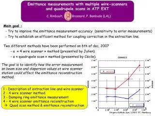
Exercising emittance measurements in the ATF EXT line. J. Brossard / C. Rimbault / P. Bambade (LAL) http://flc-mdi.lal.in2p3.fr/. Upgrade of Annecy meeting slides …. ATF EXT line description & wire scanner position. 90°. 5 positions for wire scanners.

E N D
Exercising emittance measurementsin the ATF EXT line J. Brossard / C. Rimbault / P. Bambade (LAL) http://flc-mdi.lal.in2p3.fr/ Upgrade of Annecy meeting slides ….
ATF EXT line description& wire scanner position 90° 5 positions for wire scanners Each position is equipped with 3 wire scanners oriented at 0, 90 and 10° for y,x and 10° beam-size measurement. 10° 0° Wire thickness = 10 mm & 50 mm Diagnostic section (hx=hy =0) Diagnostic section (hx=hy =0)
Evolution ofHorizontal & Vertical sqrt(beta) and phase functions along EXT line for nominal and modified EXT line. QM7
Horizontal&Verticalbeam size at wire-scanner positions for nominal and modified EXT mad deck. y=2.10-11 m y= y(s) y=sqrt(yy) Wire thickness = 10 mm x=2.10-9 m x= x(s) x=sqrt(xx) Wire thickness = 50 mm
Exercice : Run MAD with QM7 = Nominal value & QM7 = QM7-20% Remark : Only the K1 value is modified What about the dipole kick induce by the x-offset position in the quad ? At each wire scanner the beam matrix is computed (output from MAD) . A relative gaussian error on 11 33 13 is added (for 1000 succesives « measurements »): Where varie from 0 to 30 Assuming no x-y coupling for nominal case ( =0) At present time, we assume that : 13= 10°
The « 2D-emittance » reconstruction method is base on 3 different over-estiminated linear systems : Example for x measurement Beam matrix element at the reference input point A. Measurement of x at the 5 wire scanners (obtained with MAD deck where QM7=QM7-20%) Rij Linear transport coefficent (using QM7 nominal value) 10° measurements to defined 4 5 7 and 8 y measurements to defined 6 9 and 10 The Least Means Square Method (LMS) is used to find « the LMS solution ». Then the 2D projected emittancex and y are computed using :
4D intrinsinc emittances If is diagonalisable then Then the 2D projected emittancex and y are computed using :
4D intrinsinc emittances BUT …. Preliminary results…. Some mathematical point in MATLAB need to be understand. Rejection level :
Next step : Modified the 10° measurement simulation using a tracking particles. END
4d - reconstruction method based on 5 wire scanner measurements 4d-beam matrix at point A : 4d-beam matrix at point B : Where is the 4D-linear optic matrix from point A to point B.
4d - reconstruction method based on 5 wire scanner measurements If the 4d-linear transport matrix from point A to B is uncoupled Then =(x-beam size @ B)2 =(y-beam size @ B)2 -> For « n » points (B,C,…Z), where the x beam size is measure, we have : If we know how to solve this linear system then, we can compute the horizontal emittance : Similar analysis can be performed to estimate : 4, to 10 … and y can be estimated.
4d - reconstruction method based on 5 wire scanner measurements If n<3 No solution. If n==3 and Mx-1 exist then the solution is known and unique. If n>3 the sytem is « overestimated » and the Least Mean Square (LMS) method can be used to find the « LMS » solution. (in ATF n==5) First question : How sensitive to wire scanner errors this method is ? Second question : What happen if the QM6 quadrupole strength is reduce by 20% ?
First question : How sensitive to wire scanner errors this method is ? Assumption : the relative error level on « measurements » at position MW0X, MW1X, MW2X, MW3X and MW4X is identical, and tested for values ranging between 0 and 30% Where « r » comes from a gaussian distribution having zero mean and X/100 rms The minimum relative error level for y-beam size measurement is at least equal to 13% (D/4~1.25 microns)
First question : How sensitive to wire scanner errors this method is ? For each error level, 1000 « measure » have been tested. The plot shows the mean and +/- 1 rms rms value mean value The maximum relative errors (define by the rms value) on 11, 12, 22, 33, 34 and44 values are approximatively between -30% and +30%
First question : How sensitive to wire scanner errors this method is ? Impact on horizontal and vertical emittance reconstruction … This method leads to underestimate vertical and horizontal emittance. A part of the 1000 tested « measurements » lead to a unphysical results. In the current analysis, this rejection level is always lower than 4%. The underestimation of horizontal emittance is higher than the vertical one.
The maximum error level on 11, 12, 22 and 44 is similar to the previous analysis (i.e : +/- 30%) The maximum error level on 33 and 34 reach +100 or +200% !!! Second question : What happen if the QM6 quadrupole strength is reduce by 20% ? QM6 is the first bending magnet (with quadrupole part) after the kicker. The quad. strength of this element might have been over-estimated…(TBC)
Second question : What happen if the QM6 quadrupole strength is reduce by 20% ? Absolute values (m.rad) Absolute values (m.rad) relative values (%) Impact on horizontal and vertical emittance reconstruction … + 30% • In presence of WS error, the • horizontal emittance is sligthly underestimated • vertical emittance is greatly over-estimated. The rejection part increase… to reach 40% for error measurement of 30 %
Quadrupole Strengh Variation method - 1 5 positions for wire scanners QD6X MW3X MW2X s11(mm2) s11(mm2) ex= 0.00201837 mm.mrad ex= 0.00201428 mm.mrad Preliminary
Quadrupole Strengh Variation method - 2 5 positions for wire scanners QD6X MW3X MW2X s33(mm2) s33(mm2) ey= 2.01626e-05 mm.mrad ey= 2.0164e-05 mm.mrad Preliminary
Conclusions and perspectives Conclusions and persepctives - For the nominal ATF-EXT line, the LMS* method based on the 5 existing wire scanners induced an underestimation of the vertical and horizontal emittance (function of WS error level). - If the QM6 quadrupole strength is underestimated (by 20%) then the LMS method based on the 5 existing wire scanner induced a « small » horizontal emittance reduction and a « large » vertical emittance estimation (function of WS error level). For QM7 quadrupole strength underestimation an symetric (x-y) effect is observed (see extra slide). - Compare the error sensitivity of the LMS reconstruction method with a « quadrupole strength variation » method. Questions - What are the real « quadrupole strength » of QM6 and QM7 (seen by the extracted bunch) ? - Is it possible to determine WS positions leading to less error sensitive reconstruction method ? - What is the sensitivity of « quadrupole strength variation » method ? (which quad ? which WS ?, new quad position ?, new WS position ? ….). - Is it possible to realize more than 3 measurement per WS to reduce the error level ? - others ideas ? … * LMS : Least Mean Square
References Many thanks toMark Woodley for the input MAD file (see : http://www.slac.stanford.edu/~mdw/ATF/EXT.mad) References : ATF Internal reports : ATF-99-01, ATF-00-06, ATF-99-17, ATF-99-08, ATF-00-01…
Extra-slide Absolute values (m.rad) Absolute values (m.rad) Relative values (%) QM6 quadrupole strength is reduce by 20% + 30% QM7 quadrupole strength is reduce by 20% (see M. Alabau Pons & al. Talk) + 10%