Comprehensive Analysis of Pumps in Power Plants
290 likes | 583 Vues
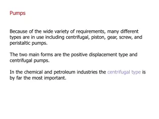
Explore the role of pumps in power plants, including major equipment, expectations, losses, matching parameters, and anatomy of centrifugal pumps. Learn about the layout, static head, NPSH, and more. Study the selection process for pump design and speed optimization.

Comprehensive Analysis of Pumps in Power Plants
E N D
Presentation Transcript
Analysis of Pumps P M V Subbarao Professor Mechanical Engineering Department I I T Delhi Machines to Convert Shaft Power to Micro Kinetic Power…….
Pump services in Main Steam Cycle • Turbogenerator and auxiliaries • Condenser circulating pumps • Screen wash-water pumps • Cooling tower make-up pumps • Steam generator equipment • Condensate pumps • Condensate booster pumps • Boiler-feed pumps • Boiler-feed booster pumps • Deaerator make-up pumps • Heater drain pumps (low and high pressure)
Rhyd,2 Rhyd,1 Rhyd,n pOFWH+ploss Expectations from A Condensate Pump Duty: Generate Required Open Feed water Heater Conditions ! Condensate Pump OFWH Hot Well
Rhyd,SG plive steam Rhyd,1 Rhyd,n ploss+plive water Steam Turbine Expectations from A Boiler Feed Pump To Generate Required Live Steam Conditions ! BF Pump OFWH / DA
Cross-section, single 48.5 MW boiler feed pump, 1300 MW fossil power plant
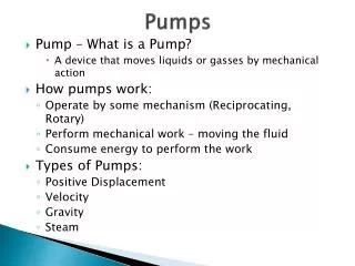
Power Losses in Pump • Head losses due to suction and delivery pipe fittings, entrance losses, impeller frictional losses and casing frictional losses. • Power loss due Leakages and recirculating fluid. • Disc Friction loss • Mechanical Losses
Machine-Fluid Matching Parameter Design Parameter
SELECTION OF SPEED A pump/fan with a given flow geometry and momentum transfer principle
Selection of Geometry Vs Specific Speed Specific Speed
Specific Speed Vs Flow Geometry& Principle of Momentum Transfer Mixed Axial Flow / Airfoil Action Radial Fow/ Centrifugal Action
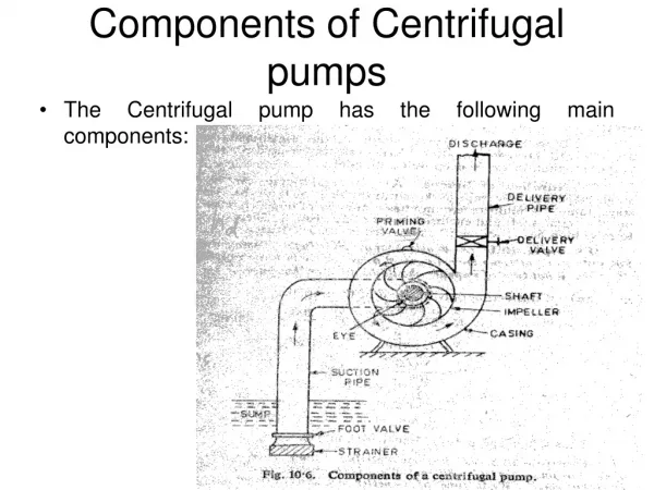
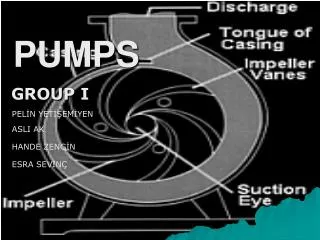
Anatomy of A Centrifugal Pump/Fan : Low Ns Discharge Nozzle - K Impeller - J Shaft - C Eye of Impeller - G Casing - F
Basic Erection of A Pump STATIC SUCTION HEAD
Variation of Absolute Pressure inside A Pump pabsolute Flow Path
NPSH NPSH
Kinetic power mVs2/2 Frictional loss in suction piping Available NPSH At Site
Specific Speed Vs Suction Velocity Suction Velocity: