Download
1 / 35
350 likes | 563 Vues
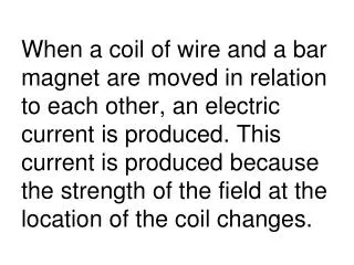
It is sometimes difficult to find the polarity of an induced emf. The net magnetic field penetrating a coil of wire results from two factors.

E N D
It is sometimes difficult to find the polarity of an induced emf. The net magnetic field penetrating a coil of wire results from two factors.
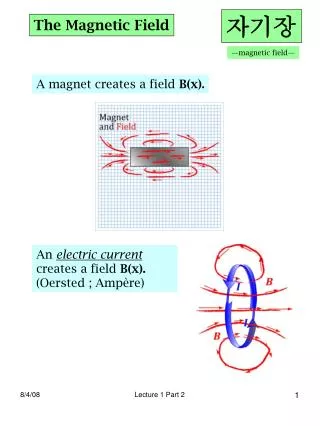
One is the original magnetic field that produced the changing flux that leads to the induced emf. The other comes from the fact that the induced current produces its own magnetic field.
The field produced by an induced current is called an induced magnetic field.
Lenz’s Law states that the induced emf resulting from a changing magnetic flux has a polarity that leads to an induced current whose direction is such that the induced magnetic field opposes the original flux change.
This three step strategy helps find the direction of the induced emf:1. Determine whether the magnetic flux that penetrates a coil is increasing or decreasing.
2. Find what the direction of the induced magnetic field must be to oppose the change in flux by adding to or subtracting from the original field.
3. After finding the direction of the induced magnetic field, use RHR-2 to find the direction of the induced current. Then the polarity can be found (conventional flow from + to -).
Ex. 8 - A permanent magnet approaches a loop of wire. The external circuit attached to the loop consists of the resistance R. Find the direction of the induced current and the polarity of the induced emf.
Ex. 9 - There is a constant magnetic field in a rectangular region of space. This field is directed perpendicularly away from us. Outside this region there is no magnetic field. A copper ring, perpendicular to the direction of the field, slides through the region. The ring is completely outside the region, partway through, completely inside, partway out, and completely out at different times of its motion. For each of the five positions: is there an induced current?, and what is its direction?
An ac generator consists of a coil of wire spinning in a magnetic field. The equation for the emf produced is:ε = N(2BLv sin θ). This can be written using angular speed as: ε = ε0 sin wt, where w = 2πf and E0 = NABw.
The polarity of the coil alternates as it spins, so this electric generator is called an alternating current (ac) generator.
Ex. 10- The coil of an ac generator rotates at a frequency of f = 60.0 Hz and develops an emf of 120 V (rms). The coil has an area of A = 3.0 x 10⁻³ m2. and consists of N = 500 turns. Find the magnitude of the magnetic field in which the coil rotates.
Ex. 11 - A generator is mounted on a bicycle to power a headlight. A small wheel on the shaft of the generator is pressed against the bike tire and turns the armature 44 times for each revolution of the tire. The tire has a radius of 0.33 m. The armature has 75 turns, each with an area of 2.6 x 10⁻³ m2, and rotates in a 0.10-T magnetic field. When the peak emf being generated is 6.0 V, what is the linear speed of the bike?
The devices connected to a generator are called the “load”. If no devices are connected, the only force from the generator is that needed to mechanically move the loop. However, if devices are connected, the induced current produces a magnetic force F called a countertorque.
This countertorque opposes the motion and requires more force to be added to the generator. The greater the current, the more force must be applied.
When an electric motor is operating, two sources of emf are present: (1) the applied emf V that drives the motor, and (2) the emf ε induced by the generator-like action of the rotating coil.
This induced emf ε acts to oppose the applied emf V as Lenz’s law predicts. It is called the back emf or the counter emf of the motor.
V and ε have opposite polarities, so the net emf in the circuit is V-ε. The current I drawn by the motor is V-ε /R.
Ex. 12 - The coil of an ac motor has a resistance of R = 4.1 Ω. The motor is plugged into an outlet where V = 120.0 volts (rms), and the coil develops a back emf of ε = 118.0 volts (rms) when rotating at normal speed. The motor is turning a wheel. Find (a) the current when the motor first starts up and (b) the current when the motor is operating at normal speed.
A changing current (ac, for example) in a coil of wire can produce an emf in a nearby coil. The initial coil is called the primary coil and is an electromagnet that produces a magnetic field. This field creates a magnetic flux in the secondary coil.
This production of current in another circuit is called mutual induction. The net magnetic flux in the secondary coil is N2F2, and is proportional to the change in current ∆I1in the primary coil.
Using a proportionality constant M (mutual inductance), an equation is created: N2F2 = MI1. This can be substituted into Faraday’s law to form:ε2 = -M∆I1/∆t.
ε2 = -M∆I1/∆tThis is the emf produced in a secondary coil due to mutual induction.
The unit of mutual inductance is V•s/A, which is called a henry (H). It is usually found experimentally for coil geometry and core material, if present.
An ac current in a coil produces a changing magnetic field which, in turn, creates a changing flux through the coil. This is self-induction.
Using a constant L, called the self-inductance of the coil, we find that:ε = -L ∆I/∆t.This is the emf due to self-inductance.
Ex. 13 - A long solenoid of length l = 8.0 x 10⁻² m and cross-sectional area A = 5.0 x 10⁻⁵ m2 contains n = 6500 turns per meter. (a) Find the self-inductance of the solenoid, assuming the core is air. (b) Determine the emf induced in the solenoid when the current increases from 0 to 1.5 A in a time of 0.20 s.
A transformer uses mutual induction and self-induction to increase or decrease the ac voltage. In a high-quality transformer: εS/εP = NS/NP. This is because the rate of change of flux is equal in both coils and cancels out.
High-quality transformers have negligible resistance, so the emfs are nearly equal to the voltages. The equation εS/εP = NS/NP becomes: VS/VP = NS/NP. This is the transformer equation.
The average power in both coils is constant, and P = IV. Therefore:IP/IS=VS/VP = NS/NP
A transformer that steps up the voltage simultaneously steps down the current, and vice-versa. However, the average power remains constant.
Ex. 14 - A step-down transformer has 330 turns in the primary coil and 25 turns in the secondary coil. It is connected to a 120-V wall socket, and there is a current of 0.83 A in the primary coil. Find (a) the voltage across the secondary coil, (b) the current in the secondary coil, and (c) the average electrical power delivered to the circuits connected to the secondary coil.