Download
1 / 29
620 likes | 1.36k Vues
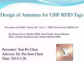
Design of Antennas for UHF RFID Tags. Proceedings of the IEEE (Volume:100 , Issue: 7 ) RFID Virtual Journal, IEEE2012.07. By Etienne Perret , Member IEEE, Smail Tedjini , Senior Member IEEE, and Raji Sasidharan Nair, Student Member IEEE. Presenter: Yen-Po Chen

E N D
Design of Antennas for UHF RFID Tags Proceedings of the IEEE (Volume:100 , Issue: 7 ) RFID Virtual Journal, IEEE2012.07 By Etienne Perret, Member IEEE, SmailTedjini, Senior Member IEEE, and RajiSasidharan Nair, Student Member IEEE Presenter: Yen-Po Chen Advisor: Dr. Pei-Jarn Chen Date: 2014.3.26
Introduction • Radio-frequency identification (RFID) technology is one of the major methods for identification purposes. • Its operating principle was very clearly explained by Harry Stockman in an IRE publication of 1948. • One of the early application is the identify friend or foe (IFF).
RFID tags are more compact and more complex . • Based on an integrated circuit (IC, commonly known as the RFID chip), which embeds in the same passive components such as analog, radiofrequency (RF), and digital circuitry. • Today ISO standards are accepted worldwide and allow a certain level of interoperability between equipment coming from different sources. • A real high degree of interoperability is still missing in applications particularly using ultrahigh-frequency (UHF) bands.
Two main factors should be underlined for tag designers • First, RF regulations are not the same worldwide. • Indeed, contrary to high-frequency (HF) RFID for which there exists a single frequency band adopted worldwide, there are at least three frequency bands for UHF RFID depending on specific country regulations. • Inaddition to that, the emission power and the communication channel parameters are not the same for different geographic regions.
Chip less RFID tags (also named RF barcodes) can be considered as an emerging area of RFID technology for ultralow-cost RFID applications. • The first realized chip less tags are based on surface acoustic wave (SAW)substrate , many other low-cost approaches are under development .
The second factor is due to the characteristics of antenna in general. • The role of the tag antenna and its impact on the global performance of the tag is very critical. • So, for any antenna there are two operating regions: near-field and far-field depending on the communication distance between reader and tags.
principle of operation of RFID • The principle of operation of a passive RFID system is illustrated • It usually contains two parts: RFID reader and an RFID tag. • The tag consists of an antenna and an application specific in-tegrated circuit (ASIC) chip. • Both exhibit complex impedances Za and Zc, respectively.
The tag can operate in the interrogation zone of the reader. • When it receives the modulated signal with sufficient power from the reader , the tag switches the chip impedance between two states and . • At each impedance state, the RFID tag presents a specific complex radar cross section (RCS). • The tag generates the information back by varying its input impedance and thus modulating the backscattered signal .
chip impedance • In practice, to maximize the tag read range, the antenna impedance Za is matched to the chip impedance at the threshold power Pth. • When the distance becomes too short, the incident power on the tag can be very important and can cause a significant variation in the chip impedance, which in turn causes an impedance mismatch and a dead zone. • Hence, more emphasis should be given to the antenna design process regarding the impedance mismatch.
While considering the frequency regulation, if we want to make a tag that operates worldwide,it must be able to operate globally in the band 860–960 MHz. • The information provided by the chip manufacturer is often incomplete. is only available from an equivalent circuit model, at the threshold power,Where, for a given capacitance C, and a series resistance Rc. • The variation of the chip impedance with power and frequency can drastically affectthe performance of the tag.
Purposes • The sensitivity of the antenna is certainly one of the major weaknesses of UHF tags. • This feature can be used to improve the efficiency of the label sensing apparatus. • In fact it has proved in certain designs, RFID tags can obtain good sensing capabilities. • There are two main aspects will be studied: the stability and sensing .
Material and Methods • UHF RFID passive tags is to match the impedance of the antenna in order to transfer maximum power to the chip. • An antenna optimization should be required in order to achieve such an antenna design. • In practice, we consider that the reader should always be able to collect the information from the tag as long as the chip receives sufficient power and then is activated. • However, perfect matching cannot be achieved in practice. • The best way is to minimize the power reflection coefficient or to maximize the read range r.
In order to satisfy the design requirements. • Hence, miniaturization techniques must be implemented. • The most popular method of miniaturization is simply to fold the arms of the dipole in order to get the desired template as well as good EM features. • Also since the material on which the tag will be attached is unknown, traditional antenna design approaches cannot be applied directly. • One possible way is to test different antenna topologies until we get the solution for the initial problem.
Conventional Antenna Design • Conventional antenna design approach,three distinct steps
The specific design of a working 2. 45 GHz of RFID dipole antenna • Half-wave dipole antenna model • Antenna copper material (conductivity: 5.8e7s/m,permeability: 1) • Located in the center of the cube filled with air in the outer surface of the cube is set radiation absorbing boundary. • The input signal is fed into the center of the antenna, which is the location of the RFID chip.
For 2. 45 GHz operating frequency of the half-wave length of about 61mm, the dipole antenna provided to the arm width w of 1 mm, and an infinitely thin, the width of the antenna arms, and called the actual length of a half-wave dipole antenna was 57mm. • An soft HFSS tools on the platform, using the finite element method to simulate the antenna input return loss distribution obtained radiation field E plane (ie the plane of maximum radiation direction and the electric field vector is located).
Can be seen from the right in the axial direction of the antenna, the antenna is almost no radiation if at this time in the direction of the reader, the transponder will not make any response in order to obtain a full range of the radiation antenna to overcome this drawback, You can make the appropriate deformation of the antenna, • Such as the extension on the end of a vertical dipole antenna arm in the direction indicated K / 4 as shown in this way to modify the total length of the antenna (57. 0 mm + 2 @ 28. 5 mm), the antenna arm width remains 1 mm. Antenna arms extend after K / 4, the antenna resonating at a wavelength, rather than the original half-wavelength.
This allows the input impedance of the antenna is greatly increased, the simulation results about 2 k Ω. Input return loss in FIG. • Of E-plane radiation pattern (antenna plane), where the solid lines show the simulation results, black dot is the actual sample measurement data, both of which are more consistent with the results illustrate that the design is correct.
In the design of the antenna was found to have a correlation between the change in the antenna topology changes, the geometrical dimensions and electromagnetic properties of the antenna. • In the antenna geometry, such as research arm length of the radiating element parameters such as pitch, a goodunderstanding of the electrical characteristics of thesupplied antenna. • The choice of the form of embodiment of the antenna is the most important step, since the final performance is entirely dependent on the initial geometry.
Preliminary Results • AUTOMATED ANTENNA DESIGN TOOL • A fully automated shape generation (FASG) coupled with the evolutionary programing technique based on the genetic algorithm (GA) . • This antenna design approach guarantees to obtain a large panel of antenna topologies and generate original shapes. • Due to FASG and contrary to the conventional antenna design, the users do not have to suggest any initial antenna shape; • Definition of [the complex impedance of the chip (Z0c )], the minimum power activation , and concerning the tag environment.
A. Fully Automated Shape Generation • The idea is to generate the most varied shapes of antennas with a limited number of unknown parameters. • Thus, the presented antenna generation approach is based on the class of folded wire structures. • This antenna generation approach allows obtaining meanders (which intend to reduce the length of the antenna) and offers the possibility of getting loops.
The chip location in the structure can move, and isthus optimized. To generate antennas, we just have to definea vector of parameters to describe the antenna shape: / N: the elementary wire number / Lw: the elementary wire width / Cp: the chip location / two parameters defining the position of each wire to another • To construct each wire, consider two points A and B
B. FASG Coupled With GA • The GA is the core of the automated design process. • Evaluation of the antenna consists of two steps: • 1) EM characteristics of the antenna are obtained using An soft Designer • 2) fitness function • that takes into account both the initial specifications and EM characteristics of the antenna returns a value that describes the performance of the antenna.
Topology evolution, as a function of GA generation. Only one part of the antennas is shown. • For each generation,the shown antenna corresponds to the largest fitness function.
Conclusions • The tag design should meet numerous constraints due to RFID chip characteristics: low cost and small size requirements. • In addition to that, there are specific standards and RF emission regulations . • The latter regards frequency allocation and emission level that are different from region to region worldwide. • So designed UHF RFID tag antenna. It is still a very challenging problem
REFERENCES • [1] H. Stockman, BCommunication by means of reflected power,[ Proc. IRE,vol. 36, no. 10, pp. 1196–1204, Oct. 1948. • [2] K. Finkenzeller, RFID Handbook: Fundamentals and Applications in ContactlessSmart Cards, Radio Frequency Identification and Near-Field Communication. New York: Wiley, 2010. • [3] Perret, E. and Tedjini, S. ; Nair, R.S. Design of Antennas for UHF RFID Tags Proceedings of the IEEE (Volume:100 , Issue: 7 ) RFID Virtual Journal, IEEE • [4] http://tcnwo.blogspot.tw/p/rfid-chips.html