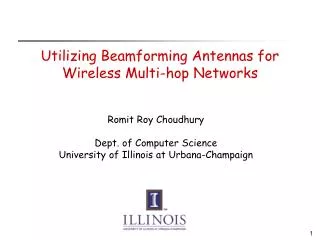
Utilizing Beamforming Antennas for Wireless Multi-hop Networks
1.11k likes | 1.39k Vues
Utilizing Beamforming Antennas for Wireless Multi-hop Networks. Romit Roy Choudhury. Internet. Applications. Several Challenges, Protocols. Internet. Omnidirectional Antennas. RTS = Request To Send. CTS = Clear To Send. IEEE 802.11 with Omni Antenna. M. Y. S. RTS. D. CTS. X. K.

Utilizing Beamforming Antennas for Wireless Multi-hop Networks
E N D
Presentation Transcript
Utilizing Beamforming Antennas for Wireless Multi-hop Networks Romit Roy Choudhury
Internet Applications Several Challenges, Protocols
Internet Omnidirectional Antennas
RTS = Request To Send CTS = Clear To Send IEEE 802.11 with Omni Antenna M Y S RTS D CTS X K
IEEE 802.11 with Omni Antenna silenced M Y silenced S Data D ACK silenced X K silenced
D G B F C Y A E silenced silenced silenced silenced silenced silenced silenced silenced IEEE 802.11 with Omni Antenna silenced M `` Interference management `` A crucial challenge for dense multihop networks S Data D ACK silenced X K silenced
Managing Interference • Several approaches • Dividing network into different channels • Power control • Rate Control … New Approach … Exploiting antenna capabilities to improve the performance of wireless multihop networks
B F C A Y D G E silenced silenced silenced silenced silenced silenced silenced silenced From Omni Antennas … silenced M S D silenced X K silenced
Y D E A C F B G To Beamforming Antennas M S D X K
Y D E A C F B G To Beamforming Antennas M S D X K
Today • Antenna Systems A quick look • New challenges with beamforming antennas • Design of MAC and Routing protocols • MMAC, ToneDMAC, CaDMAC • DDSR, CaRP • Cross-Layer protocols – Anycasting • Improved understanding of theoretical capacity • Experiment with prototype testbed
Antenna Systems • Signal Processing and Antenna Design research • Several existing antenna systems • Switched Beam Antennas • Steerable Antennas • Reconfigurable Antennas, etc. • Many becoming commercially available For example …
Electronically Steerable Antenna [ATR Japan] • Higher frequency, Smaller size, Lower cost • Capable ofOmnidirectional modeandDirectional mode
Switched and Array Antennas • On poletop or vehicles • Antennas bigger • No power constraint
Antenna Abstraction • 3 Possible antenna modes • Omnidirectional mode • Single Beam mode • Multi-Beam mode • Higher Layer protocols select • Antenna Mode • Direction of Beam
A Antenna Beam • Energy radiated toward desired direction Main Lobe (High gain) A Sidelobes (low gain) Pictorial Model
Directional Reception • Directional reception = Spatial filtering • Interference along straight line joining interferer and receiver C C Signal Signal A B A B Interference D Interference D No Collision at A Collision at A
Will attaching such antennas at the radio layer yield most of the benefits ? Or Is there need for higher layer protocol support ?
We design a simple baseline MAC protocol (a directional version of 802.11) We call this protocol DMAC and investigate its behavior through simulation
DMAC Example • Remain omni while idle • Nodes cannot predict who will trasmit to it Y S D X
RTS DMAC Example • Assume S knows direction of D Y S D X
RTS CTS RTS DATA/ACK X silenced … but only toward direction of D DMAC Example Y S D X
Intuitively Performance benefits appear obvious
However … Throughput (Kbps) Sending Rate (Kbps)
Clearly, attaching sophisticated antenna hardware is not sufficient Simulation traces revealed various new challenges Motivates higher layer protocol design
Antenna Systems A quick look • New challenges with beamforming antennas • Design of MAC and Routing protocols • MMAC, ToneDMAC, CaDMAC • DDSR, CaRP • Cross-Layer protocols – Anycasting • Improved understanding of theoretical capacity • Experiment with prototype testbed
New Challenges [Mobicom 02] Self Interference with Directional MAC
Unutilized Range • Longer range causes interference downstream • Offsets benefits • Network layer needs to utilize the long range • Or, MAC protocol needs to reduce transmit power Data A D B C route
Utilize Range – MMAC • Learn far away neighbor via ngbr discovery • Approaches proposed in literature • Send RTS packets over multiple DO links • Request Rx to beamform back toward Tx • Tx sends Data over DD link, followed by DD Ack
New Challenges II … New Hidden Terminal Problems with Directional MAC
New Hidden Terminal Problem • Due to gain asymmetry • Node A may not receive CTS from C • i.e., A might be out of DO-range from C CTS RTS Data B A C
New Hidden Terminal Problem • Due to gain asymmetry • Node A later intends to transmit to node B • A cannot carrier-sense B’s transmission to C CTS RTS Data Carrier Sense B A C
New Hidden Terminal Problem • Due to gain asymmetry • Node A may initiate RTS meant for B • A can interfere at C causing collision Collision Data RTS B A C
New Challenges II … New Hidden Terminal Problems with Directional MAC
New Hidden Terminal Problem II • While node pairs communicate • X misses D’s CTS to S No DNAV toward D Y S Data Data D X
New Hidden Terminal Problem II • While node pairs communicate • X misses D’s CTS to S No DNAV toward D • X may later initiate RTS toward D, causing collision Collision Y S Data D RTS X
New Challenges III … Deafness with Directional MAC
Deafness • Node N initiates communication to S • S does not respond as S is beamformed toward D • N cannot classify cause of failure • Can be collision or deafness M Data S D RTS N
Channel Underutilized • Collision: N must attempt less often • Deafness: N should attempt more often • Misclassification incurs penalty (similar to TCP) M Data S D RTS N Deafness not a problem with omnidirectional antennas
Deafness and “Deadlock” • Directional sensing and backoff ... • Causes S to always stay beamformed to D • X keeps retransmitting to S without success • Similarly Z to X a “deadlock” Z DATA RTS S D RTS X
New Challenges IV … MAC-Layer Capture The bottleneck to spatial reuse
Capture • Typically, idle nodes remain in omni mode • When signal arrives, nodes get engaged in receiving the packet • Received packet passed to MAC • If packet not meant for that node, it is dropped Wastage because the receiver could accomplish useful communication instead of receiving the unproductive packet
C C D D A B A B B and D beamform to receive arriving signal Capture Example Both B and D are omni when signal arrives from A
Outline / Contribution • Antenna Systems A closer look • New challenges with beamforming antennas • Design of MAC and Routing protocols • MMAC, ToneDMAC, CaDMAC • DDSR, CaRP • Cross-Layer protocols – Anycasting • Improved understanding of theoretical capacity • Experiment with prototype testbed
C C D D A B A B Impact of Capture Beamforming for transmission and reception only is not sufficient Antenna control necessary during idle state also
MAC Layer Solution • Capture-Aware MAC (CaDMAC) • D monitors all incident traffic • Identifies unproductive traffic • Beams that receive only unproductive packets are turned off • However, turning beams off can prevent useful communication in future C D A B
CaDMAC Time Cycles • CaDMAC turns off beams periodically • Time divided into cycles • Each cycle consists of • Monitoring window + 2.Filtering window cycle 1 2 1 2 1 2 time All beams remain ON, monitors unproductive beams Node turns OFF unproductive beams while it is idle. Can avoid capture
C D A B CaDMAC Communication C • Transmission / Reception uses only necessary single beam • When node becomes idle, it switches back to appropriate beam pattern • Depending upon current time window D A B
Spatial Reuse in CaDMAC • During Monitoring window, idle nodes are omni C D E A B F
Spatial Reuse in CaDMAC • At the end of Monitoring window CaDMAC identifies unproductive links C D E A B F