Logic-Based Programming for Wireless Sensor-Actuator Networks: Simplifying CPS Design
This paper introduces SAN-Logic, a lightweight programming paradigm aimed at enhancing the dynamic programmability of sensor-actuator interactions within wireless sensor networks supporting Cyber-Physical Systems (CPS). By modeling interactions as boolean expressions rather than separate sub-programs, SAN-Logic simplifies the design process and facilitates efficient deployment across large sensor networks. The framework merges logic programming with network optimization techniques to enable flexible and scalable systems, promoting ease of integration with existing networking infrastructure.

Logic-Based Programming for Wireless Sensor-Actuator Networks: Simplifying CPS Design
E N D
Presentation Transcript
Logic-based programming for wirelesssensor-actuator networks Yizhi Wu, Anthony Rowe Electrical and Computer Engineering Department Carnegie Mellon University Presented by: Yogesh Sur CS ID: ysur@cs.odu.edu
About the Authors • Dr. Anthony Rowe • Assistant Research Professor Electrical and Computer Engineering and CyLabCarnegie Mellon University • His research focuses on networked real-time embedded systems for sensing and control applications • Dr. Yizhi Wu • RF software engineer at Qualcomm
Abstract This paper presents SAN-Logic, a lightweight logic-based programming paradigm that enables the dynamic programmability and configuration of sensor-actuator interactions in wireless sensor networks used to support Cyber-Physical Systems (CPS). The goal is to simplify complex CPS design by providing a structured model of interactions that can be automatically mapped and deployed to a sensor-actuator network in an efficient and scalable manner. In contrast to sensor networking paradigms that distribute an application into individual sub-programs, SAN-Logic models the system as a set of booleanexpressions which can be partitioned across the network like gates in a circuit. The user defines interactions as timed asynchronous sequential logic expressions with sensors and actuators representing the inputs and outputs of the system.
Key Terms • Asynchronous: Of or requiring a form of computer control timing protocol in which a specific operation begins upon receipt of an signal • Sequential logic: It is a type of logic circuit whose output depends not only on the present value of its input signals but on the past history of its inputs. • HVAC: Heating, ventilation and air conditioning • Message Passing: In this model ,processes or objects can send and receive messages (comprising zero or more bytes, complex data structures, or even segments of code) to other processes.
Index • Introduction • Related Work • Architecture • Network Optimizations • Limitations • Example Application • References
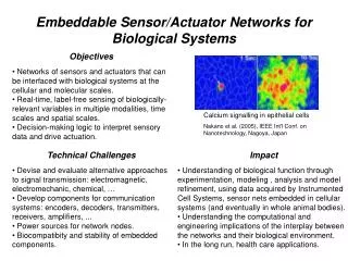
Introduction • Wireless sensor networks provide a means for an easy-to-deploy sensing and communication infrastructure • Nodes equipped with sensors and actuators can be configured to perform tasks ranging from lighting control to HVAC regulation. • Modern building HVAC systems are comprised of hundreds of sensor and actuator elements that communicate over expensive wired buses • To become a practical tool for CPS environments, a framework is required for designing and deploying such networks
Introduction: Problems with present Networks • The current approach for programming sensor networks typically involves adding individual tasks that are tied together through explicit message passing. • Application code is tightly integrated with the majority of the functionality focused on the networking layer. • It becomes quite complex and time-consuming to implement CPS applications with unique in-network interactions
Introduction: Solution Scheme in this paper • This paper presents SAN-Logic (Sensor-Actuator Network Logic), a design paradigm based on logical programming used to build CPS applications. • This adopts adopt a dataflow-centric architecture where changing values in the system force the recalculation of other variables • Interactions are represented as boolean expressions enabling the system to be managed and optimized using existing VLSI and control automation tools • SAN-Logic is extremely lightweight and can operate on top of an existing sensor networking infrastructure. • Highly scalable across large sensor networks since different subsections can run independently from their surrounding nodes
Introduction: Motivation for using Boolean Logic • One of the major motivations for using boolean logic is the ability to leverage existing VLSI design tools. • Boolean manipulation of sensor-actuator logic can be used to assign blocks of logic to specific physical locations • Techniques like expression decomposition can identify faults which can be bought to the attention of the designer before deployment.
Related Work • Virtual machines provide the basis of a flexible platform for supporting macro-programming. • Mate is a stack-based virtual machine loosely based on the Forth programming language. • The VM was designed to support safe and energy-efficient dynamic reprogramming of nodes. • The Token Machine Language (TML) is similar to Mate except that executable in TML are compiled down to a binary intermediate form that is executed on each node • TML uses an execution and communication model based on token passing where computation is triggered by the arrival of tokens which, in turn, change state stored in shared memory • The simplicity of dual-state logic optimization in SAN-logic is largely responsible for the adoption of binary logic in digital design rather than a larger number of basic states.
Architecture • Logic Synthesis: This sub-system optimizes and validates the input logic without using topology information. Common expressions can be combined and errors like race conditions can be identified • Topology Synthesis and Mapping: This optimized logic is then passed to a topology mapping stage where logic is again synthesized but is used in conjunction with topology information. • Logic Dispatcher: Finally, the system description is packetized into individual components that need to run on each node and dispatched to them over the network. Each node runs a local Logic Engine that is responsible for evaluating and reacting to inputs
Architecture: Language Primitives • In this case, signal x is configured to be dependent on the value of a or the inverse of b. • The rising-edge delay is set to 0ms with a FIFO policy. This means that when the inputs produce a TRUE signal, the message is sent immediately. • The falling-edge is governed by a cancel policy which means that if the signal changes within the timeout period of 10 seconds, the FALSE signal will be deleted. • This means that the inputs must be stable for more than 10 seconds before the output can go from high to low.
Architecture: Logic Designer • Relay Ladder Logic (RLL) is used as a graphical diagram-based language that connects components like elements in a circuit that can be captured as a subset of SAN-Logic
RLL Representation • In RLL, the rungs are executed sequentially
Architecture: Logic Synthesizer • There are two primary logic synthesis steps that are used to optimize designs • The first is a logic synthesis step that operates on the input logic without any notion of topology • During this stage, the boolean expressions are manipulated to factor out common terms and reduce the number of literals and operators in an expression • Next, a synthesis step occurs that uses topology information collected from the sensor network.
Architecture: Verification • One of the most fundamental verification requirements is the ability to determine if one circuit is functionally identical to another which is called equivalence checking • Equivalence checking can be used to perform sanity checks on optimized components, or to compare functionality of a circuit with that of a reference design • Verification techniques are beyond the scope of this paper
Architecture: Logic Engine • The logic engine is responsible for arbitrating all input and output signals based on the given logic expressions and sensor-actuator configurationsbased on the given logical expression.
Architecture: Logic Engine • Signals received as packets by the node are passed to the logic engine and in turn any generated signals from the logic engine are passed to the network. • The Logic Engine will only transmit signals if their state has changed, or if there is an explicit request for state updates from neighbors. • The logic expressions for each node are stored as Reverse Polish Notation (RPN) expressions that are created by the dispatcher and addressed to each specific node in the network. • The signal TX queue is used to store signals in accordance with their timing parameters.
Architecture: Logic Engine Implementation • Implementation of SAN-Logic was designed to run on top of the Nano-RK real-time operating system. • Each component to be designed as a separate concurrent task. • The dotted rectangle indicates the components that are part of Nano-RK that simply support the logic engine.
Network Optimizations • Manipulation of expressions using boolean algebra can be used to adjust network performance • The paper focuses on energy reduction. • It shows that that by combining common terms and intelligently mapping them the number of messages required to react to changing inputs can be greatly reduced
Network Optimizations: Topology Mapping • Passing all relevant sensor inputs to their associated actuator output nodes does not capitalize on the ability to manipulate the underlying logic expressions which may contain common terms • Additional terms can be added to expressions that do not change their functionality, but simply provide a means of moving message passing patterns around in the network
Network Optimizations: Topology Mapping • The expression x = ab, where x is an actuator while a and b are sensors. • By adding an intermediate term to (a) and mapping that to the topology, messages are passed as shown in (b) with the addition of signal t1.
Network Optimizations: Literal Reduction and short-circuited expressions • All logic expressions can be represented as a two level Sum-Of-Products (SOP) where each input is AND’ed together forming intermediate values that are passed to a single OR gate. • The problem with this approach is that many AND gates are needed to encode the entire truth-table. • Intermediate node location is biased towards the inputs and not the outputs is because many times if the expression is locally evaluated and does not change, additional messages can be avoided
Network Optimizations: Literal Reduction and short-circuited expressions
Network Optimizations: Coping with Packet Loss • Standard approach of using link-level acknowledgments and retries to increase reliability • A device only transmits in case of a state change • To increase reliability, nodes will also periodically rebroadcast state information • This paper uses average retry count at each node • Nodes with low retry counts would rarely send out periodic updates, while node with higher retry rates would more frequently send messages
Limitations • SAN-Logic is best suited for systems with binary variable values. • Non-binary values can be passed using the signal bus construct that allows multiple signals to represent individual bits of a variable. • Extensive use of wide buses will incur significant synthesis time overhead • Sequential logic optimization systems suffer from scaling due to issues of NP completeness
References • Logic-based programming for wireless sensor-actuator networks, ICCPS 2011, YizhiWu, Anthony Rowe