Download
1 / 23

E N D
1. 4. Setting-out of a circular arc it is used for linear constructions (roads, railways, regulated watercourses)
a circle is most often used, a transition curve is usually inserted between the straight section and the circle (for fluent passing)
A clothoid (Euler�s spiral) is the transition curve for roads and a cubic parabola is the transition curve for railways.
1
2. Setting-out of the main points of a circular arc A circle is generally defined by 3 elements (usually by 2 tangents t1, t2 and by the radius r).
Horizontal angle ? is measured and the central angle a is calculated: a = 200 gon � ?. 2
3. The main elements of a circular arc (calculated using r and a):
length of the tangent t = r . tg (? / 2)
rise of the arc
3. rectangular coordinates of the central point of the arc (related to the tangent) xV = r . sin (? /2) ,
yV = r . (1� cos (? /2)).
4. length of the arc 3
4. The main points of an arc = ZO, V, KO
The beginning (point ZO) and the end (point KO) of the arc are set out from the intersection of the tangents (point VB) by means of the tangent length. The central point of the arc V is set out either by means of the rise of the arc in the direction of the angle ? /2 or by means of the rectangular coordinates related to the tangent. 4
5. Setting-out of detailed points of a circle arc:
from polar coordinates
from semipolar coordinates
5
6. Setting-out of detailed points of a circular arc from polar coordinates Detailed points are set out from the points ZO or KO.
Setting-out elements: horizontal angle ? horizontal distance s0i 6
7.
It is useful to choose the lengths of the arc between nearby points s identical, then
?i = i . ?
?i = i . ? 7
8. Setting-out of detailed points of a circular arc from semipolar coordinates when a total station is not available
the horizontal angle ? is set out from the point ZO (like at the polar method), but the distance is set out from the foregoing detailed point. It is possible to use a tape for the setting-out of the distance because the distance is usually shorter than 20 m. 8
9. Setting-out of heights Setting-out of points of a horizontal plane or of a horizontal straight line
Setting-out of points of a sloping straight line
Setting-out of a contour line 9
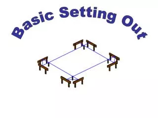
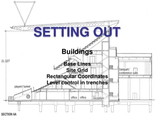
10. 1. Setting-out of a horizontal straight line At first a position of the straight line is set out and its points are marked by stakes.
HN � planned height 10
11. A levelling line is connected to 2 height points HVB1 and HVB2 at least and the absolute height of the horizon of the instrument HS is determined :
HS = HHVB1 + z1 = HHVB2 +�z2 �
Hi = HS ��pi
qi = HN ��Hi �
+ qi � filling
� qi � cutting
The calculated values qi are written at stakes and to the setting-out plan. 11
12. Setting-out of a horizontal plane First of all positions of several parallel straight lines are set out. A distance between the straight lines is constant. Points of the straight lines are marked by stakes. These points are measured by surface levelling and earthworks qi are calculated using mentioned formulas. 12
13. 2. Setting-out of a sloping straight line a) setting-out of a sloping straight line whose gradient s % is given and which comes through a given point,
b) setting-out of a sloping straight line connecting two given points 13
14. a) Given: point A, planned height of the straight line at point A (HNA), direction of the straight line and its gradient s %.
Points 1, 2, � of the straight line are marked in fixed distances a (e.g. 10 m) by stakes.
A levelling line is connected to 2 height points HVB1 and HVB2 at least and the absolute height of the horizon of the instrument HS is determined
HS = HHVB1 + z1 = HHVB2 +�z2 �
Heights of points are determined by levelling Hi = HS ��pi 14
15. Planned heights of points 1, 2, � are calculated:
HN1 = HNA���? , ? = a . s % / 100.
HN2 = HNA���2? , the definition of the gradient:
HN3 = HNA ��3? ,
HNi = HNA���i? . 15
16. Fillings or cuttings:
qA = HNA ��HA�= HNA ��HS�+ pA ,
qi = HNi � Hi�= HNi ��HS�+ pi
The calculated values qi are written at stakes and to the setting-out plan. 16
17. b) Setting-out of a sloping straight line connecting two given points The procedure is similar to the previous one, in addition to that the gradient has to be calculated using planned heights of the beginning and the end points A and B and their distance d:
h = HNA - HNB
17
18. 3. Setting-out of a contour line for water buildings where the reservoir border line has to be set out. 18
19. A levelling line starts at the height point HVB1. The line is measured to a point where the horizon of the instruments HS is from 1 to 2 m higher than the planned contour line height HN.
Q � reading which should be on the rod standing on wanted contour line:
Q = HS ��HN
The reading Q is marked on the rod by a sliding target or by an elastic belt. 19
20. A lineman moves with the rod around demanded place till the horizontal line of sight comes through the centre of the target.
The point of the contour line is marked by a stake, points are usually needed in distances from 30 m to 50 m. 20
21. Geodetic legal regulations in the Czech Republic Act No. 200/1994 Coll., on Surveying and Mapping + decree No. 31/1995 Coll. 21
22. Content of the act and the decree there is a definition of �geodetic activity�, a list of warrants and duties for performing of geodetic activities, who can practise land survey activities (graduates from a secondary school or an university with a view to land surveying)
verification of results of land survey activities � authorized surveying engineer
authorized surveying engineer � university education, land survey specialization, master�s degree at least and then 5-year practice at least, successful passing a test of professional qualification 22
23. Verification of results of land survey activities � examples:
creation of a setting-out net
execution of a setting-out plan
setting-out of construction size and shape
measurement of shifts (vertical, horizontal) and deformations of a construction
23