ATF Damping Ring Beam Development
ATF Damping Ring Beam Development. 2010.02.12 K. Kubo. ATF Damping Ring の主な目標. Final Focus Test (ATF2) からの要請 Low vertical emittance, e y < 12 pm Stable beam, jitter << beam size Fast Ion instability の研究からの要請 Low vertical emittance, e y ~ 5 pm Stable beam, jitter << beam size

ATF Damping Ring Beam Development
E N D
Presentation Transcript
ATF Damping RingBeam Development 2010.02.12 K. Kubo
ATF Damping Ring の主な目標 • Final Focus Test (ATF2) からの要請 • Low vertical emittance, ey< 12 pm • Stable beam, jitter << beam size • Fast Ion instability の研究からの要請 • Low vertical emittance, ey~ 5 pm • Stable beam, jitter << beam size (現状: single bunch ではほぼOKだが、multibunch での不安定性などの系統的なデータがまだない。) • ILC DR design と同程度の低エミッタンス • ey = 2 pm (現状: 5 pm 程度は確認できているが、2 pm は未確認。)
Low Emittance Tuning Monitor: • 補正のための情報 • BPM (Beam Position Monitors) 、total 96 • Turn by turn BPM (tune measurement) • エミッタンスの確認 • Beam size monitors • SR-interferometer • X-ray SR profile monitor • Laser Wire monitor
Low Emittance Tuning Corrector: • Steering magnets • 47 horizontal and 51 vertical • Skew Qauds • Trim coils of sextupole magnets, total 68
+ I - I /2 - I /2 - I /2 - I /2 + I Skew correctors - trim coils of sextupole magnets The trim windings of all 68 sextupole magnets have been arranged to produce skew quadrupole fields, used as correctors. Currents of the top and the bottom poles are the same. Currents of other poles are one half. (Suggested by T. Raubenheimer) Skew Quad Field by Sextupole Magnet Figure by Okugi
SR interference beam size monitor Interference pattern 6
X-ray SR beam size monitor (Tokyo Univ., KEK) Beam image (x:39µm, y:7.3µm) 7
Routine of Low Emittance Tuning Three consecutive corrections • COD correction • Vertical COD-dispersion correction • minimize dispersion and orbit simultaneously with weights • Coupling correction • minimize vertical orbit change by horizontal steerings
Simulated vertical emittance Magnet offset: measured + 30 micron BPM-magnet offset: 200 micron Magnet rotation: 0.3 mrad BPM rotation: 20 mrad COD+Dispersion+coupling Distribution from 500 random seeds Number of entries COD+Dispersion COD ey (pm)
Example of Low emittance data in ATF DR Vertical emittance measured by Laser Wire (April 16, 2003) 10 8 6 4 2 0 vertical emittance (pm) by Y. Honda 0 1 2 3 4 bunch current (mA) By 2004, we confirmed very low emittance beam, around 4 pm.
Intensity dependence Measurement compared with simulation with Intra-beam scattering Energy spread Bunch length
Recent efforts for low emittance ey ~ 5pm確認後、低エミッタンスの追及はATFの主要な課題でなくなり、2007-2008年には通常の補正では20 pm程度のエミッタンスにしかならない状態であった。 Main motivation: ATF2 needs low emittance beam (12 pm at N~1E10 in design) Study of Fast Ion Instability • Re-alignment of magnets • Reset optics • BBA (Beam Based Alignment) measurement • Optics correction (Beta-beat correction) • Improvement of BPM • Improvement of beam size monitors (各項目がどの程度有効であったか、定量的評価はできていない。)
Re-alignment of DR magnets RMS deviation from smooth curve: 80 micron 50 micron Spec: 60 micron from “smooth curve” by M. Takano
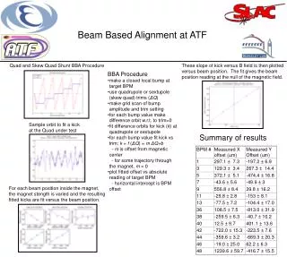
Beam Based Alignment Simulation of the tuning showed importance of BPM - magnet center offset error Emittance vs. BPM offset error with respect to the nearest magnet
Magnet (quad or skew quad) BPMs BPMs BPM Beam Based Alignment - Method Fig. by Okugi • Make vertical local bump at the Magnet-BPM. • 2. Change Magnet strength. • 3. Measure the orbit difference for all BPMs. • Normal Quads: Vertical, Skew Quads: Horizontal • 4. Estimate the minimum orbit difference point. Trim windings of sextupole magnets
Beam Based Alignment - results Typical statistical error of offset evaluated from pulse to pulse jitter: ~ 30 mm for Quad ~ 80 mm for Skew Quad Long term Stability Difference between April 2008 and April 2009. Significant change in one year for some BPM-magnet pairs. Probably came from BPM electronics.
Optics matching (Beta-beat Correction) Calculated vertical beta functions of two different optics matching conditions. December 1999, when we observed small vertical emittance (about 5pm). May 2008, when we could not achieve low emittance. Beta-beat increase emittance sensitivity to errors. Reset optics to “design” and correct optics looking betafunction (Not completely successful but some improvement.)
Damping Ring BPM electronics upgrade • Closed orbit 測定精度の向上 • Turn-by-turn データの取り込みが可能 • 現在、96個中20個のBPMで交換済 • 残り76個は今年中に交換予定 • BBA, Orbit, Dispersion, Coupling cor. 等の精度向上 • Turn by turn data の解析によるCoupling Correction • Optics 診断の精度向上
ビームサイズモニターの性能向上 ビームサイズモニターの主要な役割 • 補正の各ステップの有効性の評価 (Tuning by try and error.) • 低エミッタンスの確認 問題点 • SR interferometer, X-ray profile: 測定限界が6ミクロン程度 (エミッタンスにして 10 pm 程度)。 • Laser Wire モニター: 測定に時間がかかる(調整終了後5~10分程度)ため、補正の各ステップでの評価に使いずらい。
ビームサイズモニターの性能向上(2009年) • SR interferometer • 光路の再アラインメント • スリット間隔 40 mm 60 mm ~4 micron vertical beam size • X-ray SR profile monitor • 機械的振動の低減 ~4 micron vertical beam size • Laser Wire • Storage mode だけでなく通常の運転(ビーム取り出し)モードでも測定できるように変更 • ビームタイムを占有することなく測定可能 (測定に要する時間は長い) 今後、レーザーの交換(大出力)の計画あり • 測定時間の短縮
Recent Vertical Emittance history (preliminary)
For smaller emittance (~2 pm) • BPM electronics upgrade • BBA • ORM analysis • New correction method • Normal mode analysis • Beam size monitor improvement
ORM (Orbit Response Matrix) Analysis • 各 steering magnet を変えて orbit を測定 • モデルとの比較により、エラーを推定できる • Quadrupole strengths, • BPM gains and couplings, • Corrector magnet strengths and tilts. Can be used for Optics correction (Quad strength) Coupling correction (minimize HV response) 過去Optics correctionに使われ、ある程度成功していた。 しかし、最近あまり有効でない(BPM electronics, 又はopticsの再現性などの問題か)。 要検討
lab y normalmode y normalmode x lab x Tuning methodUsing turn-by-turn BPM Data • To “calibrate” a BPM, we can observe turn-by-turn normal mode motion on the beam, e.g. by “shaking” the beam first at one betatron frequency, then at the other. • This allows us to determine the components of beam motion along the normal mode axes, regardless of any gain errors. • If the dispersion is parallel to the “horizontal” normal mode, then quantum excitation will not excite any motion in the “vertical” normal mode: this is the optimum condition for minimising the vertical emittance. • The effects of dispersion and coupling are fixed simultaneously. by Andy Wolski
lab y normalmode y normalmode x lab x • BPM “Calibration” • ビームをキックして turn-by-turn データをとる。 • 各BPMについて、周波数成分の解析により、Normal mode の方向を決める。 • Correction • 各BPMで vertical like normal mode の dispersion が小さくなるように skew quad corrector をセットする。 • 上の2つを繰り返す(skew quad corrector を変えると normal mode の方向も変化する。)
Tuning Simulation Results 2% BPM gain errors. No BPM calibration. Distribution peaks at ~ 12 pm. (4個の電極毎のエラー) 10% BPM gain errors. With BPM calibration. Distribution peaks at ~ 1.2 pm. by Andy Wolski
Stability 目標: • pulse to pulse jitter < beam size • (At IP of ATF2: < 0.3sin vertical) • bunch to bunch jitter << beam size (multibunch 運転) • (At IP of ATF2: < 2 nm, 0.05sin vertical) 現状: • Single bunch 運転では問題なし • Multibunch 十分なデータがまだない。
Single bunch ビームの安定性Synchrotron and betatron oscillation estimated from orbit data of many pulses (single bunch) Longitudinal: 0.2s Horizontal: ~0.08s Vertical: 0 ~ 1s (large error due to BPM resolution) Energy jitter
Multibunch ビームの安定性 なぜ必要か • Final focus line (ATF2)でのbunch-by-bunch feedback によるビームの安定化の実証のため。(< 0.05 s) • Fast Kicker による安定したビーム取り出しの実証のため。 • Ring での Fast Ion Instability の研究のため。(他の原因による不安定性は抑えなければならない。) 現状 • Single bunch に比べて jitter が大きいが、系統的なデータがほとんどない。 • 真空度に関係がある。 • バンチ数、fill パターンに依存。 • intensity に依存。 • Tune のわずかな変更には反応しない。 • Simulation では、Cavity Wakefield による instability はないはず。 • . . . . . . .
まとめ 低エミッタンス(single bunch) • 補正直後 ey10 pm 以下 (about 5 pm) は確認できる。 • Better than design assumption of ATF2 • Good enough for Fast Ion Instability test. • 長期間保持できるかどうかの系統的データが必要 • BPMのcalibration, BBA, Optics 診断などの方法、有効性について、引き続き研究が必要。 • For smaller emittance (~ 2pm、ILCの設計値) • Upgrade of BPM electronics • New correction method will be tried • Beam size monitor improvement (e.g. laser wire upgrade) ビームの安定性 • Single bunch ではOK • Multibunch では今後の研究が必要。
Routine of Low Emittance Tuning • COD correction: using steering magnets, minimize BPM reading and , :x(y): horizontal (vertical) BPM reading. (b) V-COD-dispersion correction: using steering magnets, minimize dispersion and orbit y: measured vertical dispersion. r : weight factor = 0.05 (c) Coupling correction: using skew quads, minimize vertical response to horizontal steering x(y): horizontal (vertical) position change at BPM due to excitation of a horizontal steering magnet. Two horizontal steering magnets were used (Nsteer=2). About (n+1/2)p phase advance between the two.
Reset optics andBeta-beat Correction Vertical beta-function at all quadrupole magnet of one family in the arc sections. (Should be flat for matched optics.) Before and after a beat correction. (Example) Condition was improved but not completely satisfactory. Need more study for better modeling.
DR BPM resolution improvement by digital read-out system (SLAC, FNAL, KEK) beam position read-out vs. beam intensity: scattered plot : existing analog circuit. line plot : digital read-out introduced for test. aiming εy ~ 1 pm Digital read-out Stored Beam – 10 minute time scale; ATF lifetime ~ few minutes Analogue read-out
Plans • If turn-by-turn data are available, BPM calibration against normal mode motion is fast and quite straightforward. • Good quality calibration data have been obtained at CesrTA; but correction is difficult in CesrTA because there are few skew quadrupoles. • ATF BPMs should be upgraded with Echotek electronics (for turn-by-turn measurements) during the course of 2010. • initial tests with some Echoteks already installed indicate impressive performance (resolution, stability...) • It is hoped to test the calibration and tuning method later this year, when the new BPMs are available. • The proposed technique is a development of the “gain mapping” that has been used successfully to calibrate the BPMs and improve the optics tuning in KEKB. by Andy Wolski