Download

1 / 44
450 likes | 484 Vues
Learn about the importance of Cohesive Zone Modeling (CZM) in understanding fracture mechanics of materials. Explore how CZM offers an alternative way to model failure and its applications in various fields. See the historical development, mathematical principles, and applications of CZ models.

E N D
Theoretical and Computational Aspects of Cohesive Zone Modeling NAMAS CHANDRA Department of Mechanical Engineering FAMU-FSU College of Engineering Florida State University Tallahassee, Fl-32310 AMML
What is CZM and why is it important • In the study of solids and design of nano/micro/macro structures, thermomechanical behavior is modeled through constitutive equations. • Typically is a continuous function of and their history. • Design is limited by a maximum value of a given parameter ( ) at any local point. • What happens beyond that condition is the realm of ‘fracture’, ‘damage’, and ‘failure’ mechanics. • CZM offers an alternative way to view and failure in materials.
Fracture/Damage theories to model failure • Fracture Mechanics - • Linear solutions leads to singular fields-difficult to evaluate • Fracture criteria based on • Non-linear domain- solutions are not unique • Additional criteria are required for crack initiation and propagation • Basic breakdown of the principles of mechanics of continuous media • Damage mechanics- • can effectively reduce the strength and stiffness of the material in an average sense, but cannot create new surface
CZM is an Alternative method to Model Separation • CZM can create new surfaces. • Maintains continuity conditions mathematically, despite the physical separation. • CZM represents physics of the fracture process at the atomic scale. • It can also be perceived at the meso- scale as the effect of energy dissipation mechanisms, energy dissipated both in the forward and the wake regions of the crack tip. • Uses fracture energy(obtained from fracture tests) as a parameter and is devoid of any ad-hoc criteria for fractureinitiation and propagation. • Eliminates singularity of stress and limits it to the cohesive strength of the the material. • It is an ideal framework to model strength, stiffness and failure in an integrated manner. • Applications: geomaterials, biomaterials, concrete, metallics, composites….
Development of CZ Models-Historical Review Figure (a) Variation of Cohesive traction (b) I-inner region,II-edge region • Molecular force of cohesion acting near the edge of the crack at its surface (region II ). • The intensity of molecular force of cohesion ‘f ’ is found to vary as shown in Fig.a. • The interatomic force is initially zero when the atomic planes are separated by normal intermolecular distance and increases to high maximum after that it rapidly reduces to zero with increase in separation distance. E is Young’s modulus and is surface tension • Barenblatt(1959)was first to propose the concept of Cohesive zone model to brittle fracture (Barenblatt, G.I, (1959), PMM (23) p. 434)
Dugdale (1960) independently developed the concept of cohesive stress • For Ductile metals (steel) • Cohesive stress in the CZM is equated to yield stress Y • Analyzed for plastic zone size for plates under tension • Length of yielding zone ‘s’, theoretical crack length ‘a’, and applied loading ‘T’ are related in the form (Dugdale, D.S. (1960), J. Mech.Phys.Solids,8,p.100) AMML
Phenomenological Models • The theory of CZM is based on sound principles. • However implementation of model for practical problems grew exponentially for practical problems with use of FEM and advent of fast computing. • Model has been recast as a phenomenological one for a number of systems and boundary value problems. • The phenomenological models can model the separation process but not the effect of atomic discreteness. • Hillerborg etal. 1976 Ficticious crack model; concrete • Bazant etal.1983 crack band theory; concrete • Morgan etal. 1997 earthquake rupture propagation; geomaterial • Planas etal,1991, concrete • Eisenmenger,2001, stone fragm- • entation squeezing" by evanescent waves; brittle-bio materials • Amruthraj etal.,1995, composites • Grujicic, 1999, fracture beha-vior of polycrystalline; bicrystals • Costanzo etal;1998, dynamic fr. • Ghosh 2000, Interfacial debo-nding; composites • Rahulkumar 2000 viscoelastic fracture; polymers • Liechti 2001Mixed-mode, time-depend. rubber/metal debonding • Ravichander, 2001, fatigue • Tevergaard 1992 particle-matrix interface debonding • Tvergaard etal 1996 elastic-plastic solid :ductile frac.; metals • Brocks 2001crack growth in sheet metal • Camacho &ortiz;1996,impact • Dollar; 1993Interfacial debonding ceramic-matrix comp • Lokhandwalla 2000, urinary stones; biomaterials
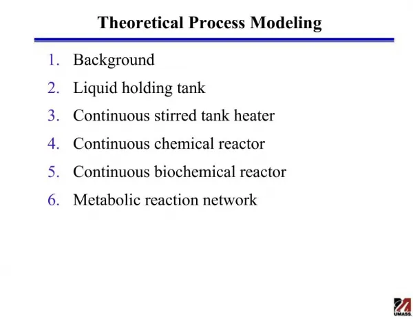
Fracture process zone and CZM Mathematical crack tip Material crack tip x • CZM essentially models fracture process zone by a line or a plane ahead of the crack tip subjected to cohesive traction. • The constitutive behavior is given by traction-displacement relationship, obtained by defining potential function of the type y where are normal and tangential displacement jump The interface tractions are given by
Critical Issues in the application of CZM to interface models • What is the relationship between the physics/mechanics of the separation process and shape of CZM? (There are as many shapes/equations as there are number of interface problems solved!) • What is the relationship between CZM and fracture mechanics of brittle, semi-brittle and ductile materials? • What is the role of scaling parameter in the fidelity of CZM to model interface behavior? • What is the physical significance of • - Shape of the curve C • - tmax and interface strength • - Separation distance sep and COD? • - Area under the curve, work of fracture, fracture toughness G (local and global)
Motivation for studying CZM critical issues addressed here • Scales- What range of CZM parameters are valid? • MPa or GPa for the traction • J or KJ for cohesive energy • nm or for separation • displacement What is the effect of plasticity in the bounding material on the fracture processes Importance of shape of CZM Energy- Energy characteristics during fracture process and how energy flows in to the cohesive zone. CZM is an excellent tool with sound theoretical basis and computational ease. Lacks proper mechanics and physics based analysis and evaluation. Already widely used in fracture/fragmentation/failure AMML
Atomistic simulations to extract cohesive properties • Motivation • What is the approximate scale to examine fracture in a solid • Atomistic at nm scale or • Grains at scale or • Continuum at mm scale • Are the stress/strain and energy quantities computed at one scale be valid at other scales? (can we even define stress-strain at atomic scales?) AMML
Embedded Atom Method EnergyFunctions (D.J.Oh and R.A.Johnson, 1989 ,Atomic Simulation of Materials, Edts:V Vitek and D.J.Srolovitz,p 233) The total internal energy of the crystal where and Internal energy associated with atom i Embedded Energy of atom i. Contribution to electron density of ith atom and jth atom. Two body central potential between ith atom and jth atom. AMML
Boundary Conditions for GB Sliding • Construct symmetric tilt boundaries (STDB) by rotating a single crystal (reflection) • Periodic boundary condition in X direction • Restrain few layers in lower crystal • Apply body force on top crystal AMML
Curve in Shear direction A small portion of CSL grain bounary before And after application of tangential force Shet C, Li H, Chandra N ;Interface models for GB sliding and migrationMATER SCI FORUM 357-3: 577-585 2001
Curve in Normal direction A small portion of CSL grain boundary before And after application of normal force AMML
Results and discussion on atomistic simulation • Implications • The numerical value of the cohesive • energy is very low when compared • to the observed experimental results • Atomistic simulation gives only surface energy ignoring the inelastic energies due to plasticity and other micro processes. • It should also be noted that the exper- imental value of fracture energy includes the plastic work in addition to work of separation (J.R Rice and J. S Wang, 1989) Summary • complete debonding occurs when the distance of separation reaches a value of 2 to 3 . • For 9 bicrystal tangential work of separation along the grain boundary is of the order 3 and normal work of separation is of the order 2.6 . • For 3 -bicrystal, the work of separation ranges from 1.5 to 3.7 . • Rose et al. (1983) have reported that the adhesive energy (work of separation) for aluminum is of the order 0.5 and the separation distance 2 to 3 • Measured energy to fracture copper bicrystal with random grain boundary is of the order 54 and for 11 copper bicrystal the energy to fracture is more than 8000
Table of surface and fracture energies of standard materials
Energy balance and effect of plasticity in the bounding material AMML
Motivation • It is perceived that CZM represents the physical separation process. • As seen from atomistics, fracture process comprises mostly of inelastic dissipative energies. • There are many inelastic dissipative process specific to each material system; some occur within FPZ, and some in the bounding material. • How the energy flow takes place under the external loading within the cohesive zone and neighboring bounding material near the crack tip? • What is the spatial distribution of plastic energy? • Is there a link between micromechanics processes of the material and curve.
Plasticity vs. other Dissipation Mechanisms • Since bounding material has its own inelastic constitutive equation, what is the proportion of energy dissipation within that domain and fracture region given by CZM. • Role of plasticity in the bounding material is clearly unique; and cannot be assigned to CZM. AMML
Cohesive zone parameters of a ductile material • Al 2024-T3 alloy • The input energy in the cohesive model are related to the interfacial stress and characteristic displacement as • The input energy is equated to material parameter • Based on the measured fracture value AMML
Material model for the bounding material Stressstrain curve is given by • Elasto-plastic model for Al 2024-T3 where E=72 GPa, =0.33, and fracture parameter AMML
Geometry and boundary/loading conditions a = 0.025m, b = 0.1m, h = 0.1m AMML
Finite element mesh 28189 nodes, 24340 plane strain 4 node elements, 7300 cohesive elements (width of element along the crack plan is ~ m AMML
is cohesive energy, a sum total of all dissipative process confined to FPZ and cannot be recovered during elastic unloading and reloading. • Purely elastic analysis • The conventional fracture mechanics uses the concept of strain energy release rate • Using CZM, this fracture energy • is dissipated and no plastic dissipation occurs, such that Global energy distribution are confined to bounding material AMML
Global energy distribution (continued) Two dissipative process Plasticity within Bounding material Micro-separation Process in FPZ • Implications • Leaves no energy for plastic work in the bounding material • In what ratio it should be divided? • Division is non-trivial since plastic dissipation depends on geometry, loading and other parameters as • Issues • Fracture energy obtained from experi-mental results is sum total of all dissipative processes in the material for initiating and propagating fracture. • Should this energy be dissipated entirely in cohesive zone? • Should be split into two identifiable dissipation processes? where represents other factors arising from the shape of the traction-displacement relations • Analysis with elasto-plastic material model
in cohesive zone dictates the stress level achievable in the bounding material. • Yield in the bounding material depends on its yield strength and its post yield (hardening characteristics. • Thus plays a crucial role in determining plasticity in the bounding material, shape of the fracture process zone and energy distribution. (other parameters like shape may also be important) What are the key CZM parameters that govern the energetics?
Recoverable elastic work 95 to 98% of external work • Plastic dissipation depends on • Elastic behavior • plasticity occurs. • Plasticity increases with Global energy distribution (continued) • Variation of cohesive energy and plastic energy for various ratios • (2) • (3) (4) AMML
(very small scale plasticity), plastic energy ~ 15% of total dissipation. • Plasticity induced at the initial stages • of the crack growth • plasticity ceases during crack • propagation. • Very small error is induced by ignoring • plasticity. • plastic work increases considerably, ~100 to 200% as that of cohesive energy. • For large scale plasticity problems the amount of total dissipation (plastic and cohesive) is much higher than 8000 • Plastic dissipation very sensitive to ratio beyond 2 till 3 • Crack cannot propagate beyond and completely elastic below Relation between plastic work and cohesive work
Variation of Normal Traction along the interface • The length of cohesive zone is also affected by ratio. • There is a direct correlation between the shape of the traction-displacement curve and the normal traction distribution along the cohesive zone. • For lower ratios the traction-separation curve flattens, this tend to increase the overall cohesive zone length. AMML
A set of patch of elements (each having app. 50 elements) were selected in the bounding material. • The patches are approximately squares (130 ). They are spaced equally from each other. • Adjoining these patches, patches of cohesive elements are considered to record the cohesive energies. Local/spatial Energy Distribution AMML
The cohesive energy in the patch increases up to point C (corresponding to in Figure ) after which the crack tip is presumed to advance. • The energy consumed by the cohesive elements at this stage is approximately 1/7 of the total cohesive energy for the present CZM. • Once the point C is crossed, the patch of elements fall into the wake region. • The rate of cohesive zone energy absorption depends on the slope of the curve and the rate at which elastic unloading and plastic dissipation takes place in the adjoining material. • The curves flattens out once the entire cohesive energy is dissipated within a given zone. Variation of Cohesive Energy The variation of Cohesive Energy in the Wake and Forward region as the crack propagates. The numbers indicate the Cohesive Element Patch numbers Falling Just Below the binding element patches
Variation of Elastic Energy • Considerable elastic energy is built up till the peak of curve is reached after which the crack tip advances. • After passing C, the cohesive elements near the crack tip are separated and the elements in this patch becomes a part of the wake. • At this stage, the values of normal traction reduces following the downward slope of curve following which the stress in the patch reduces accompanied by reduction in elastic strain energy. • The reduction in elastic strain energy is used up in dissipating cohesive energy to those cohesive elements adjoining this patch. • The initial crack tip is inherently sharp leading to high levels of stress fields due to which higher energy for patch 1 • Crack tip blunts for advancing crack tip leading to a lower levels of stress, resulting in reduced energy level in other patches. Variation of Elastic Energy in Various Patch of Elements as a Function of Crack Extension. The numbers indicate Patch numbers starting from Initial Crack Tip
Variation of Plastic Work ( ) • plastic energy accumulates considerably along with elastic energy, when the local stresses bounding material exceeds the yield • After reaching peak point C on curve traction reduces and plastic deformation ceases. Accumulated plastic work is dissipative in nature, it remains constant after debonding. • All the energy transfer in the wake region occurs from elastic strain energy to the cohesive zone • The accumulated plastic work decreases up to patch 4 from that of 1 as a consequence of reduction of the initial sharpness of the crack. • Mechanical work is increased to propagate the crack, during which the does not increase resulting in increased plastic work. That increase in plastic work causes the increase in the stored work in patches 4 and beyond Variation of dissipated plastic energy in various patched as a function of crack extension. The number indicate patch numbers starting from initial crack tip.
, there is no plastic dissipation. • plastic work is induced only in the first patch of element • No plastic dissipation during crack growth place in the forward region • Initial sharp crack tip profile induces high levels of stress and hence plasticity in bounding material. • During crack propagation, tip blunts resulting reduced level of stresses leading to reduced elastic energies and no plasticity condition. Variation of Plastic Work ( ) Variation of Plastic work and Elastic work in various patch of elements along the interface for the case of . The numbers indicates the energy in various patch of elements starting from the crack tip. AMML
Contour plot of yield locus around the cohesive crack tip at the various stages of crack growth. AMML
Schematic of crack initiation and propagation process in a ductile material
Conclusion • CZM provides an effective methodology to study and simulate fracture in solids. • Cohesive Zone Theory and Model allow us to investigate in a much more • fundamental manner the processes that take place as the crack propagates in a • number of inelastic systems. Fracture or damage mechanics cannot be used in • these cases. • Form and parameters of CZM are clearly linked to the micromechanics. • Our study aims to provide the modelers some guideline in choosing appropriate • CZM for their specific material system. • ratio affects length of fracture process zone length. For smaller • ratio the length of fracture process zone is longer when compared with that of • higher ratio. • Amount of fracture energy dissipated in the wake region, depend on shape of • the model. For example, in the present model approximately 6/7th of total • dissipation takes place in the wake • Plastic work depends on the shape of the crack tip in addition to ratio.
Conclusion(contd.) • The CZM allows the energy to flow in to the fracture process zone, where a • part of it is spent in the forward region and rest in the wake region. • The part of cohesive energy spent as extrinsic dissipation in the forward region • is used up in advancing the crack tip. • The part of energy spent as intrinsic dissipation in the wake region is required • to complete the gradual separation process. • In case of elastic material the entire fracture energy given by the of the • material, and is dissipated in the fracture process zone by the cohesive • elements, as cohesive energy. • In case of small scale yielding material, a small amount of plastic dissipation • (of the order 15%) is incurred, mostly at the crack initiation stage. • During the crack growth stage, because of reduced stress field, plastic • dissipation is negligible in the forward region. AMML