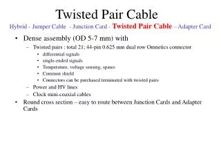
Twisted Pairs
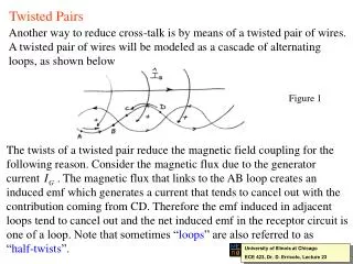
Twisted Pairs. Another way to reduce cross-talk is by means of a twisted pair of wires. A twisted pair of wires will be modeled as a cascade of alternating loops, as shown below. Figure 1. The twists of a twisted pair reduce the magnetic field coupling for the

Twisted Pairs
E N D
Presentation Transcript
Twisted Pairs Another way to reduce cross-talk is by means of a twisted pair of wires. A twisted pair of wires will be modeled as a cascade of alternating loops, as shown below Figure 1 The twists of a twisted pair reduce the magnetic field coupling for the following reason. Consider the magnetic flux due to the generator current . The magnetic flux that links to the AB loop creates an induced emf which generates a current that tends to cancel out with the contribution coming from CD. Therefore the emf induced in adjacent loops tend to cancel out and the net induced emf in the receptor circuit is one of a loop. Note that sometimes “loops” are also referred to as “half-twists”. University of Illinois at Chicago ECE 423, Dr. D. Erricolo, Lecture 23
A simple model to characterize a twisted pair consists of a cascade of rectangular loops Figure 2 Computations using this model are based upon the use of a chain parameter matrix where each loop is modeled along with the adjacent generator wire. The overall matrix for the twisted pair is obtained by multiplying the matrices for each loop while accounting for the approximate reversal of the wires at the connection from one loop to another. University of Illinois at Chicago ECE 423, Dr. D. Erricolo, Lecture 23
The twists do not reduce inherently the capacitive coupling, however capacitive coupling will be achieved if the terminations at both ends are balanced with respect to the reference conductor. We are going to consider a simple model for a twisted pair that is based on the following assumptions: 1) electrically short line; 2) weak coupling between generator and receptor circuit. Figure 3 Each loop is considered as a pair of parallel wires. and are the mutual inductances between the generator circuit and the circuit formed by one of the parallel wires and the reference conductor. The capacitances and are obtained from and . University of Illinois at Chicago ECE 423, Dr. D. Erricolo, Lecture 23
Per-unit-length parameters As previously mentioned, the mutual inductances are computed considering the circuit of the generator wire and the one between the reference wire and one of the wires of the twisted pair. Graphically, we have. Figure 4 University of Illinois at Chicago ECE 423, Dr. D. Erricolo, Lecture 23
Let us consider the following system: Figure 5 The mutual inductances are computed using the previous results for wires above a ground plane to obtain: (1) (2) (3) University of Illinois at Chicago ECE 423, Dr. D. Erricolo, Lecture 23
The other inductances are: (4) (5) (6) The capacitances are computed using the relationship (7) where the dielectric insulations have been ignored. University of Illinois at Chicago ECE 423, Dr. D. Erricolo, Lecture 23
The lumped equivalent circuit that shows all the capacitances is given in the following: Figure 6 University of Illinois at Chicago ECE 423, Dr. D. Erricolo, Lecture 23
Inductive and capacitive coupling The model for the twisted pair contains voltage sources that account for the mechanism of inductive coupling. Figure 7 and current sources that account for the capacitive coupling: Figure 8 The case shown here is referred to as being unbalanced. University of Illinois at Chicago ECE 423, Dr. D. Erricolo, Lecture 23
There are two ways to terminate a twisted pair. The “unbalanced” terminations Figure 9 where the impedance seen towards the ground by the twisted pair is different at both terminations, and the “balanced” termination Figure 10 where the impedance seen towards ground by the twisted pair is the same at both terminations. The unbalanced termination is chosen to avoid ground loops. University of Illinois at Chicago ECE 423, Dr. D. Erricolo, Lecture 23
When the twisted pair is untwisted one obtains the following equivalent circuit: Figure 11 Notice that the net induced emf is zero for an even number of loops and that of one loop for an odd number of loops. Observe that the current source near the grounding connection is shorted out. University of Illinois at Chicago ECE 423, Dr. D. Erricolo, Lecture 23
It’s easy to determine that the net current entering the wire not grounded is, for a complete twist (8) Since the twisted wires are very close to each other, we may assume: (9) and if N is the total number of twists, (10) so that the total current flowing into the ungrounded wire is approximately: (11) In this way we obtain the same amount of capacitive coupling as that of a straight pair of wires. University of Illinois at Chicago ECE 423, Dr. D. Erricolo, Lecture 23
From the equivalent circuit we obtain: (12) (13) Observe that the inductive contribution for both cross-talk transfer functions contains the term (14) which means that the inductive coupling is equivalent to the one of a straight pair of wires of length (i.e. one loop or half twist). However, the net mutual capacitance contains (15) which corresponds to the contribution coming from a straight pair of wire having the same length L of the whole line. University of Illinois at Chicago ECE 423, Dr. D. Erricolo, Lecture 23
In other words, (16) Notice that: 1) If the total number of loops is even the inductive coupling contributions from each loop cancel each other and the inductive coupling term in (16) is zero; 2) The twists do not affect the capacitive coupling with respect to a straight pair of wires. University of Illinois at Chicago ECE 423, Dr. D. Erricolo, Lecture 23
As we have previously seen, the inductive coupling is usually the dominating factor for low termination impedance circuit. So if for a pair of untwisted wires the cross-talk contributions are Figure 12 After twisting the wires we obtain Figure 13 where we observe that the total cross-talk has been reduced to the capacitive contribution. University of Illinois at Chicago ECE 423, Dr. D. Erricolo, Lecture 23
Conversely, when the terminations have large values of impedance so that capacitive coupling is the dominant contribution twisting the wires does not reduce the cross-talk since the capacitive coupling is not affected by this operation. To summarize: For unbalanced terminations, twisting the wires will reduce the cross-talk for low-impedance terminations but will not change it for high-impedance terminations. University of Illinois at Chicago ECE 423, Dr. D. Erricolo, Lecture 23
Effect of balancing A balanced termination was shown in Fig. 10. The equivalent circuit model is: Figure 14 The inductive coupling is the same as that for the unbalanced case, but The capacitive contributions cancel out and the capacitive coupling is Eliminated. So the resulting cross-talk is: inductive coupling for a straight pair of wires with the length of a single loop. University of Illinois at Chicago ECE 423, Dr. D. Erricolo, Lecture 23
Extension to transmission lines with a large number of conductors Using the matrix notation, the transmission line equations for the case of N conductors are the same, the only difference being the size of vectors and matrices that become n-by-1 and n-by-n, respectively. Computer programs have already been developed to study those cases. If fields are incident on a multiple transmission line, their effects may be included by introducing sources into a length of the transmission line. The corresponding equations become: where and are per-unit length induced sources. University of Illinois at Chicago ECE 423, Dr. D. Erricolo, Lecture 23