Download
1 / 19
190 likes | 486 Vues
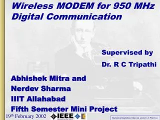
Wireless MODEM for 950 MHz Digital Communication. Supervised by Dr. R C Tripathi. Abhishek Mitra and Nerdev Sharma IIIT Allahabad Fifth Semester Mini Project. 19 th February 2002. Backdrop:Guglielmo Marconi, pioneer of Wireless. Wireless. Communication but without wires.

E N D
Wireless MODEM for 950 MHz Digital Communication Supervised by Dr. R C Tripathi Abhishek Mitra and Nerdev Sharma IIIT Allahabad Fifth Semester Mini Project 19th February 2002 Backdrop:Guglielmo Marconi, pioneer of Wireless
Wireless • Communication but without wires. • Electromagnetic Waves through Ether • Radio Waves 300KHz to 1GHz • Micro Waves 1GHz to 3THz • Light rays 3THz to 10 PHz • Some Applications • Satellite Communications • Personal Communication Systems • Wireless LAN / Bluetooth
Scope of the Project • Identify different methods for digital data transfer using Radio waves. • Search for available technologies. • Design a Wireless Modem. • Establish a Wireless Data Link between two PCs using the Modem. • Develop an Application to control the device and send / receive Data.
Chipcon CC 400 • Features: • Maximum Data Rate: 9.6 kbps Manchester Encoded. • Programmable frequency: 300-500MHz. • Output power: 14dBm, Receiver sensitivity: -112dBm. • PLL based Detector and Transmitter. • Development Kit Available.
TRF 6900A • Features: • Programmable 850MHz to 950MHz operation. • FSK / ASKModulation. • Transmit Power4.5 dbm. –85dbmReceiver Sensitivity. • High Data Rate of115.2 kbpsboth NRZ and Manchester. • DDSbased Transmitter. • Quadrature Demodulator based Detector. • Received Signal Strength Indicator. • Free SamplesAvailable from TI.
Why TRF 6900A ? • Short Listed Chips • CC 400from Chipcon. • TRF 6900Afrom TI. • Advantages of TRF6900A • Faster data rates up to115.2 kbpsversus 9.6 kbps. • Ability to handleNRZtype data versus BiPhase data. • Direct Digital Synthesizerbased design versus PLL based. • Easy availability of components for950 MHzversus 450 MHz. • Experiments already done on Chipcon boards hence quest for something new. • TRF 6900A is astate of the artchip has industrial backing. • Availability offree samplesfrom Texas instruments.
Transmitter Blocks DDS Control Word From Parallel Port Direct Digital Synthesizer PLL Crystal Oscillator @ 25 MHz Data from Serial Port Level Converter 9V to 3.3 V Power Amplifier VCO RF Out 950MHz • The computer programs the device with various parameters like frequency of operation, frequency deviation, Tx / Rx mode, etc. • The computer sends serial data to the device. • Modulated Data is transmitted as Radio Waves at 950 MHz binary(0) and 950.1 MHz binary(1).
Transmitter Section • Reference Oscillator (Clock for DDS) • Crystal Oscillator at 25 MHz. • 2. Direct Digital Synthesizer (DDS) • Generate a sine wave in the digital domain as reference to PLL. • 3. Phase Locked Loop (PLL) • Controls frequency of the VCO as per reference supplied by DDS. • 4. Voltage Controlled Oscillator (VCO) • Changes frequency according to the tuning voltage (930 MHz to 960 MHz). LC oscillator with a varactor. • Power Amplifier (PA) • Amplifies the output of the VCO to 4.5dbm (3mW)
Frequency Shift Keying Basics Binary 1 Binary 0 Binary 1 Binary 0 Binary 1 f2 f1 f2 f1 f1 Voltage Time f1 = Frequency transmitted for Binary 1 (950 MHz) f2 = Frequency transmitted for Binary 0 (950.1 MHz) f1 – f2 = Frequency Deviation (100 KHz)
FSK Spectrum The two peaks at 915.0 MHz and 915.10 Mhz demonstrate FSK.
Receiver Block Diagram FSK Demodulator IF AMP LNA RF IN 950 MHz 10.7 MHz BPF 10.7 MHz RF Mixer LPF LPF/Amplifier VCO 939.3 MHz Data Slicer At the mixer output we get sum and difference of the two frequencies as the mixer multiplies the signals. 2 COS(A)*COS(B) = COS(A+B) + COS (A-B) Data to Serial Port
Receiver Basics Phase Detector Input from IF Stage LPF A Ф B Quadrature FSK Demodulator Output of Amplifier fed to Slicer • Tuned Circuit at 10.7 MHz • No phase shift when carrier at 10.7 MHz • Phase Shift at other Frequencies (FM to AM conversion) • Low pass filtering the output recovers the data
Receiver Characteristics After Decision by Slicer 3.3 V 1.25 V Reference Demodulated Data
Our Achievements • A Plug and Play Wireless Modem. • Maximum Data Rate of 38.4 Kbps. • A range of atleast 10 meters. • WModem Control Panel Software. • IIIT Allahabad’s first wireless data communication equipment, developed in-house.
The WModem Figures showing the Wmodem • At 950 MHz PCB stray capacitance and inductance come into play. • Any copper length greater than λ/4creates trouble. • Use of CAD / CAM is inevitable.
What Else? • Enhance Data rate up to 115.2 kbps, speed of two Dial Up Modems. • Add an Amplifier to boost the output power of the device, to reach a few kilometers. • Packets in the Air: Enable sockets through wireless for TCP / IP and Internet connectivity. • Fail Safe Design: Develop a Robust Error Correction Mechanism and include a dedicated Micro-controller. • (A Software lends its reliability from the Hardware being programmed underneath) hence Hardware should be 100% reliable.
Which one would you Prefer? Wires Wireless