Download
1 / 11
150 likes | 465 Vues
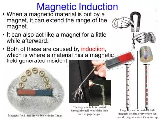
Magnetic Induction. Review of Chapter 22. Induced EMF (motional EMF). Potential difference (voltage) created by a changing magnetic field that causes current to flow through a wire.

E N D
Magnetic Induction Review of Chapter 22
Induced EMF (motional EMF) • Potential difference (voltage) created by a changing magnetic field that causes current to flow through a wire. • e = v B L where e is the electromotive force, v is the relative velocity between the charged object and the field, B is the magnetic field strength and L is the length of the object (or wire) passing through the field. • perpendicular The equation above assumes that v, B, and L are mutually
Magnetic Flux • Definition: the number of field lines that pass through an area. • FB = BA cos Q where FBis the magnetic flux, B is the magnetic field, A is the area of the region that the flux is passing through and Q is the angle between B and A • e = DF/Dt this equation for a single conductor is the basis for Faraday’s Law
Faraday’s Law • Definition: describes exactly how much EMF is induced by a changing magnetic flux. • Equation: e = -N DF Dt
Lenz’s Law • Lenz’s law describes the direction of the induced current. • Lenz stated that the direction of the induced current always opposes the increase in flux. • In other words, the induced current will create a magnetic field opposite to the existing magnetic field causing the current.
Practice Problem A circular loop of wire of negligible resistance and a radius of 20 cm is attached to the circuit shown. Each resistor has a value of 10 W. The magnetic field of the Earth point up as shown and has a value of 5 x 10⁻⁵ T. The circular loop rotates about a horizontal axis that passes through the center of the loop at a rate of 500 rev/s and remains connected to the circuit the entire time
Practice Problem (Continued) • Determine the magnetic flux through the loop when in the orientation shown in the picture. • Determing the maximum magnetic flux through the loop. • Estimate the average value of the induced EMF in the loop. • Estimate the average current in resistor C
Q1 - Magnetic Flux as shown • The flux equals zero because the field points along the loop, never going through the loop.
Q2 - Maximum Flux • Flux is at a maximum when the loop is perpendicular to the page. The flux will then be equal to B•A. B = 5 x 10⁻⁵ T A = π•r2 = π (.20)2 = .126 F = 6.3 x 10⁻⁶ Tm2
Q3 - Average EMF for the Loop e = DF/Dt, and it takes 1/4 turn to go from the minimum to maximum flux. Since it takes 1/500 of a second to make 1 turn, it only takes 1/2000 of a second to reach the first maximum. Using the equation above, the EMF is 6.3 x 10⁻⁶ Tm2 /0.0005 s = .013 V
Q4 - Current in Resistor C The circuit can now be treated as if there were a 13 mV battery attached to it. Re of resistors B and C is 5Ω and RT is 15Ω. IT = 8.4 x 10⁻⁴ A Since B and C are equal, the current is split equally among them and is 4.2x10⁻⁴ A.