Designing the Architecture
Designing the Architecture. Outline. Architecture in the life cycle Designing the architecture Forming the team structure and its relationship to the architecture Creating a skeletal system. Architecture in the Life Cycle. The evolutionary delivery life cycle Get customer feedback


Designing the Architecture
E N D
Presentation Transcript
Outline • Architecture in the life cycle • Designing the architecture • Forming the team structure and its relationship to the architecture • Creating a skeletal system
Architecture in the Life Cycle • The evolutionary delivery life cycle • Get customer feedback • Iterate through several releases, each with new or modified functionality • Deliver limited versions if necessary • When does one begin designing? • Some idea of system requirements is needed – the shaping requirements are called architectural drivers
Architecture in the Life Cycle (Cont’d) • When does one begin designing? (cont’d) • Identify the highest priority business goals and turn them into quality scenarios or use cases • The ones that have the most impact on the architecture are the architectural drivers (there should be fewer than 10) • Once the architectural drivers are known, the architectural design can begin • The requirements analysis process will then be influenced by questions generated during the architectural design,
Evolutionary Delivery Life Cycle Software Concept Deliver Final Version Preliminary Requirements Analysis Design of Architecture and System Core Develop a Version Incorporate Customer Feedback Deliver the Version Elicit Customer Feedback
Designing the Architecture • A method called Attribute Driven Design (ADD) can be used to design an architecture to satisfy both quality and functional requirements. • ADD can be viewed as an extension to other developments methods, such as the Rational Unified Process (RUP).
Attribute-Driven Design • ADD bases the decomposition process on the quality attributes the software has to fulfill. • It is a recursive decomposition process, where, at each stage, tactics and architectural patterns are chosen to satisfy a set of quality scenarios and then functionality is allocated to instantiate the module types provided by the pattern.
Attribute-Driven Design (Cont’d) • The system is described as a set of containers for functionality and the interactions among them. • This is a coarse grained framework for achieving the functionality.
Example Application of ADD • Sample problem: A garage door opener within a home information system. • The system is responsible for raising and lowering the door via a switch, remote control, or the home information system. It is also possible to diagnose problems with the opener from within the home information system.
Input to ADD • A set of requirements (typically expressed as use cases) and constraints • A set of quality requirements expressed as system-specific quality scenarios including, in this case: • The device and controls for opening and closing the door are different for the various products in the product line. They may include controls from within a home information system
Input to ADD (Cont’d) • A set of quality requirements (cont’d): • The processor used in different products will differ. • If an obstacle (person or object) is detected by the garage door during descent, it must halt (alternately re-open) within 0.1 second. • The garage door opener should be accessible for diagnosis and administration from within the home information system using a product-specific diagnosis protocol.
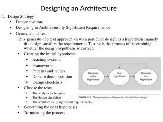
ADD Steps • Choose the module to decompose – the module to start with is usually the whole system. • Refine the module according to the following steps: • Choose the architectural drivers from the set of concrete quality scenarios and functional requirements. • Choose an architectural pattern that satisfies the architectural drivers based on the tactics that can be used to achieve the drivers.
ADD Steps (Cont’d) • Refine the module according to the following steps (cont’d): • Instantiate modules and allocate functionality from the use cases and represent using multiple views. • Define interfaces of the child modules. The decomposition provides modules and constraints on the types of module interactions. Document this information in the interface document for each module.
ADD Steps (Cont’d) • Refine the module according to the following steps (cont’d): • Verify and refine use cases and quality scenarios and make them constraints for child modules. • Repeat the steps above for every module that needs further decomposition.
1. Choose the Modules to Decompose • In our example, we start with the whole system, the garage door opener system. • One constraint at this level is that the opener must interoperate with the home information system.
2a. Choose the Architectural Drivers • The four scenarios previously given indicate requirements for: • real-time performance • modifiability to support product lines • online diagnosis • In general, a detailed investigation may be required to determine whether given requirements are really drivers.
2a. Choose the Architectural Drivers (Cont’d) • We do not treat all requirements as equal. • The less important requirements are satisfied within the constraints of the most important. • This is a significant difference between ADD and other architecture design methods.
2b. Choose an Architectural Pattern • The use of an interpreter is an excellent technique for achieving modifiability at runtime, but it has a negative influence on performance. • The decision to use an interpreter depends on the relative importance of modifiability versus performance. • A possible decision is to use an interpreter for only a portion of the pattern.
2b. Choose an Architectural Pattern (Cont’d) • The modifiability tactics are “localize changes,” “prevent the ripple effect,” and “defer binding time.” • In this case, where we are concerned primarily with changes that will occur during system design, the primary tactic is “localize changes.” • We choose semantic coherence and information hiding as our tactics and combine them to define virtual machines for the affected areas.
2b. Choose an Architectural Pattern (Cont’d) • The performance tactics are “resource demand” and “resource arbitration.” • We choose one example of each: “increase computational efficiency” and “choose scheduling policy.” • The final set of tactics is therefore: • Semantic coherence and information hiding – Separate responsibilities dealing with the user interface, communication, and sensors into their own modules (virtual machines).
2b. Choose an Architectural Pattern (Cont’d) • The final set of tactics (cont’d): • Increase computational efficiency – The performance-critical computations should be made as efficient as possible. • Schedule wisely – The performance-critical computations should be scheduled to ensure the achievement of the timing deadline.
Architectural Pattern that Utilizes Tactics to Achieve Garage Door Drivers User Interface Non-Performance- Critical Computation Performance-Critical Computation Virtual Machine Schedule that Guarantees Deadlines
2c. Instantiate Modules and Allocate Functionality Using Multiple Views • We allocate the responsibility for managing obstacle detection and halting the garage door to the performance-critical section since the functionality has a deadline. • The management of the normal raising and lowering of the door has no timing deadline so we can treat it as non-performance-critical
2c. Instantiate Modules and Allocate Functionality Using Multiple Views (Cont’d) • The diagnosis capabilities are also non-performance-critical. • Thus, the non-performance-critical module becomes instantiated as diagnosis and raising/lowering door modules. • We also identify several responsibilities of the virtual machine: communication and sensor reading and actuator control.
First-Level Decomposition of Garage Door Opener User Interface Diagnose Raising/Lowering Door Obstacle Detection Communication Virtual Machine Sensor/Actuator Virtual Machine Scheduler that Guarantees Deadlines
2c. Instantiate Modules and Allocate Functionality Using Multiple Views (Cont’d) • Applying use cases that pertain to the parent module helps the architect gain a better understanding of the distribution of functionality. • Ultimately, every use case of the parent module must be representable by a sequence of responsibilities within the child modules. • Enough must be done to gain confidence that the system can deliver the desired functionality. • The architecture should be represented by one view from each of the three major groups.
2c. Instantiate Modules and Allocate Functionality Using Multiple Views (Cont’d) • The three common views • Module decomposition view – Containers for holding responsibilities and the major flow relationships among the modules • Concurrency view – Dynamic aspects of a system such as parallel activities and synchronization can be modeled
2c. Instantiate Modules and Allocate Functionality Using Multiple Views (Cont’d) • The three common views (cont’d) • Deployment view – The virtual threads of the concurrency view are decomposed into virtual threads within a particular processor and messages that travel between processors to initiate the next entry in the sequence of actions (thus is a basis for analyzing network traffic). Additionally, this view helps to decide if multiple instances of some modules are needed and supports reasoning about special purpose hardware.
Understanding Concurrency in a System – Helpful Use Cases • Two users doing similar things at the same time • One user performing multiple activities simultaneously • Starting up the system • Shutting down the system
2d. Define Interfaces of the Child Modules • An interface of a module shows the services and properties provided and required. • It documents what others can use and on what they can depend. • Analyzing and documenting the decomposition in terms of structure (module decomposition view), dynamism (concurrency view) and runtime (deployment view) uncovers the interaction assumptions for the child modules.
2d. Define Interfaces of the Child Modules (Cont’d) • The module view documents: • Producers/consumers of information • Patterns of interaction that require modules to provide services and to use them • The concurrency view documents: • Interactions among threads that lead to the interface of a module providing or using a service • The information that a component is active • The information that a component synchronizes, sequentializes, and perhaps blocks calls
2d. Define Interfaces of the Child Modules (Cont’d) • The deployment view documents: • The hardware requirements, such as special-purpose hardware • Some timing requirements, e.g., the computational speed of a processor • Communication requirements, e.g., the information should not be updated more than once a second • All this information should be available in the modules’ interface documentation.
2e. Verify and Refine Use Cases and Quality Scenarios as Constraints for the Child Modules • Each child module has responsibilities that need to be translated into use cases for the module. Use case can also be defined by splitting and refining the parent use cases. • For the garage door opener system, the responsibilities are decomposed into the following functional groups • User interface – recognize user requests and translate them into the form expected by the raising/lowering door module
2e. Verify and Refine Use Cases and Quality Scenarios as Constraints for the Child Modules • For the garage door opener system, the responsibilities are decomposed into the following functional groups (cont’d): • Raising/lowering door module – Control actuators to raise or lower the door. Stop the door when it reaches either fully open or fully closed. • Obstacle detection – recognize when an obstacle is detected and either stop the descent of the door or reverse it.
2e. Verify and Refine Use Cases and Quality Scenarios as Constraints for the Child Modules • For the garage door opener system, the responsibilities are decomposed into the following functional groups (cont’d): • Communication virtual machine – Manage all communication with the home information system. • Sensor/actuator virtual machine – Manage all interactions with the sensors and actuators. • Scheduler – Guarantee that the obstacle detector will meet its deadlines. • Diagnosis – Manage the interactions with the home information system devoted to diagnosis.
2e. Verify and Refine Use Cases and Quality Scenarios as Constraints for the Child Modules • The constraints of the parent module can be satisfied in one of the following ways: • The decomposition satisfies the constraint, e.g., if the constraint is to use a certain operating system, by defining the operating system as a child the constraint is satisfied. • The constraint is satisfied by a single child module, e.g., if the constraint is to use a special protocol, it can be satisfied by defining an encapsulation child module for the protocol.
2e. Verify and Refine Use Cases and Quality Scenarios as Constraints for the Child Modules • The constraints of the parent module can be satisfied in one of the following ways (cont’d): • The constraint is satisfied by multiple child modules, e.g., using the Web requires two modules (client and server) to implement the necessary protocols.
2e. Verify and Refine Use Cases and Quality Scenarios as Constraints for the Child Modules • In the garage door opener system, one constraint is that the communication with the home information system is maintained. • The communication virtual machine will recognize if this communication is unavailable, so the constraint is satisfied by a single child.
2e. Verify and Refine Use Cases and Quality Scenarios as Constraints for the Child Modules • Quality scenarios also need to be refined and assigned to child modules: • A quality scenario may be completely satisfied by the decomposition without any additional impact and thereby marked as satisfied. • A quality scenario may be satisfied by the current decomposition with constraints on child modules.
2e. Verify and Refine Use Cases and Quality Scenarios as Constraints for the Child Modules • Quality scenarios also need to be refined and assigned to child modules (cont’d): • The decomposition may be neutral with respect to a quality scenario, e.g., a usability scenario, in which case it should be assigned to one of the child modules. • A quality scenario may not be satisfiable with the current decomposition. Either the decomposition should be reconsidered or rationale justifying its omission must be provided.
Refined Quality Scenarios for the Garage Door Opener Example • The devices and controls for opening and closing the door are different for different products in the product line. They may include controls from within a home information system. This scenario is delegated to the user interface module. • The processor used in different products will differ. This scenario is delegated to all of the modules. Each module becomes responsible for not using processor-specific features not supported by standard compilers.
Refined Quality Scenarios for the Garage Door Opener Example (Cont’d) • If an obstacle is detected by the garage door during descent, the door must halt (or re-open) within 0.1 second. This scenario is delegated to the scheduler and the obstacle detection module. • The garage door opener should be accessible for diagnosis and administration from within the home information system using a product-specific diagnosis protocol. This scenario is split between the diagnosis and communication modules. The communication module is responsible for the protocol to communicate with the home information system, and the diagnosis module is responsible for other diagnosis interactions.
Status at the End of the Iteration • We now have a decomposition of a module into its children. • Each child has a collection of responsibilities: • A set of use cases • An interface • Quality scenarios • A collection of constraints • This is sufficient to start the next iteration of the decomposition
Things We Still Do Not Know Regarding Our Sample Problem • The language for communication between the user interface module and the raising/lowering modules • The algorithm for performing obstacle detection • How the performance-critical section communicates with the non-performance critical section
Forming the Team Structure • Once the first few levels of the architecture’s module decomposition structure are fairly stable, those modules can be allocated to development teams. • Within teams there needs to be high-bandwidth communications. • Between teams, low-bandwidth communications are sufficient (and in fact crucial).
Forming the Team Structure (Cont’d) • If interactions between the teams is complex, either: • The interactions among the elements they are creating are needlessly complex • Or, the requirements for those elements were not sufficiently “hardened” before development commenced • Like software systems, teams should strive for high cohesion and low coupling.
Forming the Team Structure (Cont’d) • Each module of the system constitutes its own small domain (area of specialized knowledge or expertise). • This makes for a natural fit between teams and modules of the decomposition structure. • The effective use of staff, therefore, is to assign members to a team based on their expertise.
Forming the Team Structure (Cont’d) • The organizational structure also affects the architecture. • Organizational entities formed for one project are motivated to preserve their existence and will want to maximize their importance in new projects.
Creating a Skeletal System • Once an architecture is sufficiently designed and teams are in place to build it, a skeletal system can be constructed. • The architecture provides a guide as to the order in which portions of the system should be implemented. • First implement the software that deals with the execution and interaction of architectural components. • Add some simple functions. • The result is a running system onto which useful functionality can be added
Creating a Skeletal System (Cont’d) • To lower risk the most problematic functions should be added first. • Then the functionality needed to support those problematic functions is added. • This process is continued, growing larger and larger increments of the system until it is complete.