Download
1 / 62
620 likes | 842 Vues
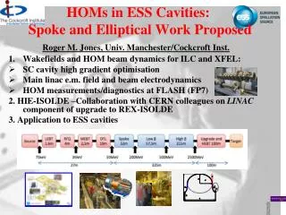
HOMs in ESS Cavities: Spoke and Elliptical Work Proposed. Roger M. Jones, Univ. Manchester/Cockcroft Inst. Wakefields and HOM beam dynamics for ILC and XFEL: SC cavity high gradient optimisation Main linac e.m . field and beam electrodynamics HOM measurements/diagnostics at FLASH (FP7)

E N D
HOMs in ESS Cavities: Spoke and Elliptical Work Proposed Roger M. Jones, Univ. Manchester/Cockcroft Inst. • Wakefields and HOM beam dynamics for ILC and XFEL: • SC cavity high gradient optimisation • Main linace.m. field and beam electrodynamics • HOM measurements/diagnostics at FLASH (FP7) 2. HIE-ISOLDE –Collaboration with CERN colleagues on LINAC component of upgrade to REX-ISOLDE 3. Application to ESS cavities
UK Membership The United Kingdom will be the 17th country to join the European Spallation Source project. The UK was welcomed today at a meeting in Bilbao, Spain, by representatives from the current 16 Partner Countries. • I am particularly happy that the UK now joins the project. The UK has a large and strong neutron research community, that will now be able to benefit from the opportunities that ESS can give, says Colin Carlile, the ESS Director-General. There is a vast knowledge of the necessary technology for building a spallation neutron source from the ion source to the instruments in the UK and there will be mutual benefits. • (source ESS news 15th April 2011)
Overview • Focus of group is on SC and NC cavities -with some other activities. (Microwave Electrodynamics and Wakefields) • SC cavities, frequency range ~ 1.3 GHz (XFEL/ILC) , 3.9 GHz (FLASH), 101 MHz (HIE-ISOLDE). • ESS spoke and 704 MHz elliptical cavities • We investigate wakefields/impedances, HOM damping, maximising gradient, computational methods.
Personnel PDRAs: Ian Shinton (Univ. Manchester), Alessandro D’Elia (Univ. Manchester/CERN), Inna Nesmiyan, TBH Ph.D. Students: Chris Glasman, Nawin Juntong, Lee Carver, Narong Chanlek, Matthew Fraser, Hugo Day , N. Shipman Graduated PhD students: Vasim Khan (now CERN Fellow) Graduated MSc students: Narong Chanlek, Chris Glasman (Univ. Manchester) Collaborators:Walter Wuensch, Alexei Grudiev, Riccardo Zennaro, Germana Riddone (CERN), Nicoleta Baboi (DESY), Ulla van Rienen (Univ. Rostock), Mats Lindroos, Steve Peggs,Steve Molloy (ESS), Toshiyasu Higo, (KEK), Graham Burt, Amos Dexter, Richard Carter (Univ. Lancaster), Valery Dolgashev (SLAC)
1. ILC High Gradient Cavities and FLASH/XFEL Third Harmonic Cavities Roger M. JonesCockcroft Institute andThe University of Manchester
LC + XFEL SC Linac -Staff • Roger M. Jones (Univ. of Manchester faculty) • Ian Shinton (Univ. of Manchester PDRA based at Cockcroft –April 2009, 100%) • Nawin Juntong (Ph.D. student, 100%) • Chris Glasman (Ph.D. student, 100%) • Part of EuCard ( European Coordination Task Leader for Accelerator Research and Development) FP7 SCLinac Task 10.5. Three associated sub-tasks. • EuCARD FP7 WP 10.5 Members: R.M. Jones, N. Baboi (DESY), U. Van Rienen (Univ. Rostock) CI/Univ. of Manchester PDRA I. Shinton (left) and Ph.D. student N. Juntong (right; supported by the Royal Thai Government and Thai Synchrotron Light Source)
Overview Two Main Parts: 1.0 Introduction to Globalised Scattering Techniques 1.1 ILC High Gradient Cavities *: New Low Surface Field Design-exploration of large parameter space 1.2 Third Harmonic Cavities at FLASH/XFEL –entails intensive simulations and construction of HOM diagnostics *Detailed beam dynamics simulations by Glasmanet al. on several alternative high gradient designs have also been conducted, but skipped here due to time constraints! Refs: 1. Juntong et al, PAC09, SRF2009 2. Shinton et al, SRF 2009
1.0 Introduction to Globalised Scattering Techniques • Simulation of Higher Order Modes (HOMs) in high gradient cavities • Utilise 3D codes: GdfidL, HFSS, ACE3P suite • Use 2D codes, ABCI, Echo2D for bulk of cavity structures. • Develop interface that cascades given sections to make more efficient calculations of overall fields. • Focus on: • Re-entrant -Cornell Univ. design • Low-loss (Ichiro variant) –KEK design. • Z. Li’s redesign
0 Cascaded Computation of EM Fields and Dispersion Relations HFSS 9-Cell Simulation Field Calc. from S-Matrix • Field distribution at interface enables rapid determination of fields and potentially trapped modes • Fields obtained from HFSS single cells cascaded Cascaded Single-Cell Ez • Dispersion Calculations via GSM enables efficient characterisation of cavities • Bethe hole perturbation coupling formulation investigated for X-band structures. Good agreement for a limited cells (thin iris approx) See Shinton and Jones, LINAC08.
1.0 HOMs studies for ILC ACD Ichiro Cavity fabricated at KEK Trapped mode ~2.4498GHz Multi-cavity mode ~2.6420GHz Simulations of E-field of the 3rd band modes in Ichiro cavities Envelope of long-range wake-field Comparison of Loss factors calculated with GdfidL (red) and MAFIA 2D (blue) Detailed studies conducted on HOMS in Ichiro cavity. Sensitivity to systematic changes in frequency investigated. Detailed comparison of codes –MAFIA,HFSS, GdfidL, Analyst. Dispersion curves of first 8 dipole and 5 sextupole bands Sensitivity of RMS wake to small changes in bunch spacing See Glasman, Jones et al. EPAC08 &LINAC08.
1.1 NLSF Design Red- Bs/Ea, Blue- Es/Ea, Black- kc Red- Bs/Ea, Blue- Es/Ea Red- Bs/Ea • Explore parameter regions for NLSF cavity with an iris range of 30 to 33 mm (whilst the iris thickness is varied). • The parameter regions for an iris of 32 mm is shown. NLSF shape 1. Surface Magnetic Field Contours 2. Surface Electric Field Contours 3. Cell coupling kc (% bandwidth)
1.1 NLSF Design - Bandwidth 1. Fundamental mode 2. Nearest mode (f8/9) closely separated:
1 NLSF Design • –Overall Surface Fields • Earlier alternate designs were limited by field emission which occurred in the end cells. • HFSS simulations indicate that NLSF cavity does not suffer from this problem. Surface Magnetic Field/Accel. Field Surface Electric Field/Accel. Field
1.1 HOM Properties of NLSF Cavity • Higher order multipoles investigated for full 9-cell cavity • Dipoles modes will dominate emittance dilution • Corresponding transverse momentum kicks studied by calculating R/Qs. • Similar, although redistributed R/Qs as TESLA shape • Modify HOM couplers (no problems anticipated!)
1.2 HOM DIAGNOSTICS IN THIRD HARMONIC CAVITIES AT FLASH Roger M. Jones University of Manchester/ Cockcroft Inst.
1.2 Task 10.5 HOM Diagnostic in 3rd Harmonic Cavities at FLASH • 10.5.1 HOM based BeamPositionMonitors (HOMBPM) • 10.5.2 HOM based Cavity Diagnostics (HOMCD) • 10.5.3 HOM based Geometrical Dependancy (HOMGD) • All pool together to ensure success of instrumentation of diagnostics for FLASH cavities.
1.2 HOM Diagnostic in 3rd Harmonic Cavities at FLASH -Staff • Sub-task leaders: NicoletaBaboi (DESY), Ursula van Rienen (Univ. Rostock), Roger M. Jones (CI/Univ. Manchester). • PDRAs: Hans-Walter Glock (Univ. Rostock), Ian Shinton (CI/Univ. of Manchester) • Ph.Ds: NawinJuntong (CI/Univ. Manchester), Pei Zhang (DESY/Univ. Manchester/CI), Thomas Flisgen (Univ. Rostock) WP 10.5.2 WP 10.5.1 WP 10.5.3 H-W Glock, Univ. of Rostock, PDRA N. Baboi, DESY U. Van Rienen, Univ. of Rostock C. Glasman, CI/Univ. of Manchester PhD student (PT on FP7) N. Juntong, CI/Univ. of Manchester PhD student (PT on FP7) I. Shinton, CI/Univ. of Manchester PDRA T. Flisgen ,Univ. of Rostock P. Zhang, DESY/Univ. Of Manchester
1.2 3.9 GHz Module Installed at FLASH TESLA Cryo-Module (ACC1) 8 x 9-Cell 1.3 GHz Cavities photo & drawing courtesy E. Vogel & FNAL ACC39 FNAL Cryo-Module 4 x 9-Cell 3.9 GHz Cavities
1.2 HOM Diagnostic in 3rd Harmonic Cavities at FLASH • Fermilabhas constructed a third harmonic accelerating (3.9GHz) superconducting module and cryostat for a new generation high brightness photo-injector. • This system compensates the nonlinear distortion of the longitudinal phase space due to the RF curvature of the 1.3 GHz TESLA cavities prior to bunch compression. • The cryomodule, consisting of four 3.9GHz cavities, have been installed in the FLASH photoinjector downstream, of the first 1.3 GHz cryomodule (consisting of 8 cavities). • Four 3.9 GHz cavities provide the energy modulation, ~20 MV, needed for compensation.
1.2 Third Harmonic Parameters Illustrative energy (not to scale) • Adding harmonic ensures the 2nd derivative at the max is zero for total field (could use any of the harmonics in the expansion, but using the lowest freq. ensures the transverse wakefields ~ 3 are minimised). • The third harmonic system (3.9GHz) will compensate the nonlinear distortion of the longitudinal phase space due to cosine-like voltage curvature of 1.3 GHz cavities. • It linearisesthe energy distribution upstream of the bunch compressor thus facilitating a small normalized emittance ~1.10-6 m*rad.
1.2 HOMs in SCRF Cavities Schematic of International Linear Collider (ILC) ~11km ~11km http://www.linearcollider.org Used at XFEL and FLASH. Baseline design for main accelerators in ILC. FPC Coupler TESLA cavity (1.3 GHz) ~1m Used at XFEL and FLASH in order to flatten the field profile and reduce energy spread. HOM Coupler 3rd harmonic cavity (3.9 GHz)
1.2 Minimising Emittance Dilution and HOMBPMs • Source of Emittance Dilution • Wt , transverse wakefields (Wt~ a-3 –a iris aperture) • Much stronger in 3.9 GHz than in 1.3 GHz cavities (each iris is r ~ 15 mm compared to 35 mm for TESLA). • Utilise Wakefields as Diagnostic • Sample HOMs to ascertain beam position (HOMBPM). • Move beam to minimise impact on itself and to align to electrical axis. • Can also be used for measuring beam charge, phase etc.
1.2 HOMs in SCRF Cavities • Higher order modes (HOMs) are excited by charge particles in cavity • ‐ influence the beam both longitudinally and transversely • ‐ non‐monopole modes excited by off‐axis particles effect bunch itself (intra) and subsequent (inter) bunches • Dipolemodesdominate transverse wake potentials • Use HOMs (non‐monopole modes) to • ‐ align the beam to the electric center • ‐ monitor beam position (HOM‐BPM) r: beam offset a: iris radius m=1, dipole; m=2, quadrupole Region of interest Earlier work on 1.3 GHz demonstrated the principle [1] G. Devanz et al., EPAC2002, WEAGB003 [2] N. Baboiet al., LINAC2004, MOP3
1.2 HOMs in SCRF Cavities HOM-couplers (pick-ups) • Task: • Develop, build, test electronics for 3.9 GHz cavities • Interpret signals and integrate in control system • Measure cavity alignment • HOM-couplers • At end of each cavity • Enable monitoring the HOMs excited by beam TESLA cavity Illustrated (similar features present in 3.9 GHz cavity)
4 cavities within 3.9GHz Module bunch compressors bypass line gun undulators FEL beam ACC39 collimator section dump 5 accelerating modules with 8 cavities each • 1.3GHz SC, typically 450-700MeV, 1 nC charge for FLASH/XFEL • HOMs generated in accelerating cavities must be damped. • Monitored HOMs facilitate beam/cavity info • Forty cavities exist at FLASH. -Couplers/cables already exist. • -Electronics enable monitoring of HOMs (wideband and narrowband response). Based on 1.3 GHz (CEA/SLAC/FNAL/DESY) Diagnostics –redesigned for ACC39 as part of EuCARD
1.2 Extant Work at 1.3 GHz: HOM-BPMs in TESLA Cavities • HOM-BPMs at 1.3GHz cavities • Use dipole mode at 1.7 GHz • Installed in 5 accelerating modules (40 cavities) • Calibration: with SVD technique • problem: unstable in time • Beam Alignment in Modules • Now routinely used in FLASH • Other studies • Cavity alignment in cryo-module • Beam phase measurement with monopole modes at ~2.4GHz • XFEL Plans: • Install in some 1.3 GHz and in all 3.9 GHz cavities
1.2 Analysis of Narrowband Signals –Beam Position (Previous 1.3 GHz Study) • Resolution of position measurement. • Predict the position at cavity 5 from the measurements at cavities 4 and 6. • Compare with the measured value. • X resolution • ~9 m • Y resolution • ~4 m
1.2 FLASH and ACC39 Free-electron LASer in Hamburg (FLASH) Photo courtesy E. Vogel & DESY Page 29
1.2 Selected Highlights • S-matrix measurements and comparison with simulations. • Transmission measurements. • Multi-cavity modes. • Beam-based mode characterisation. • HOM pickup vs beam offset for trapped/isolated modes • Comparison of analysis of data • Direct Linear Regression (DLR) vs Singular Value Decomposition (SVD)
1.2 Measurement Programme (since last SRF WP10 review meeting)
1.2 ACC39 Spectra Measured in CMTB: Focused on Dipole and Other Bands For comparison: dipole band in TESLA cavity • Transmission matrix measurements made on all 4 cavities within ACC39.
1.2 Band Structure 5thdipole band Potential HOM Diagnostic Candidates From transmission measurement done in CMTB Page 33
1.2 S21 Exp vs Simulations • Transmission through single cavity in chain. • Transmission through complete chain.
1.2 Beam-Based HOM Measurements *Not to scale Steer the beam in various ways
1.2 HOM Signal (1st Two Dipole Bands) HOM Signal (1st and 2nd Dipole Bands) • Time Domain HOM pickup • Comparison of FFT of HOM pickup vs RSA
1.2 1st Dipole Beampipe Modes • Lorentzian fit to get mode amplitude
5thDipole Cavity Band 1.2 5th Dipole Cavity Band localized! hor. move hor. move vert. move vert. move † I.R.R. Shinton, et al., “Mode Distribution …”, CI Internal Note
1.2 Comparison of DLR vs SVD 2nd dipole cavity band • Direct Linear Regression (DLR) • Singular Value Decomposition (SVD)
Direct Linear Regression 1.2 Direct Linear Regression RSA 2nd dipole cavity band • Direct Linear Regression (DLR) A: spectra matrix B: beam position matrix
1.2 Singular Value Decompostion RSA Calib. 2nd dipole cavity band • Two steps Valid.
1.2 Concluding Remarks on HOM Third Harmonic Cavities • ACC39, has been received by DESY, characterised at the CMTF, and subsequently installed at FLASH. • Beam tubes connecting cavities are above cut-off and allows for strong coupling between all 4 cavities –suite of simulations being used to characterise the coupling and sensitivity to geometrical perturbations. • Experiments indicate trapped modes in 5th band (~ 9GHz) and expected linear dependence. Mode candidate for diagnostics? First systematic comparison of DLR vs SVD indicates consistent behaviour. (other candidates are based on modes which exist in the beampipe and stretch over the complete module) • HOM electronics will be tested for 3.9 GHZ cavities in 2012. • Good overall progress!
Acknowledgements • I wish to express thanks for the organising committee for giving me this opportunity to report on the work of this task. • I acknowledge materials supplied, and/or many useful discussions with: N. Baboi, E. Vogel (DESY), P. Zhang (University of Manchester/Cockcroft Inst./DESY) , I.R.R. Shinton (University of Manchester/Cockcroft Inst.), U. Van Rienen, H.-W. Glock, T. Flisgen (University of Rostock), S. Molloy (RHUL/ESS), N. Eddy, T.N. Khabiboulline (FNAL). Publications • Higher Order Modes In Third Harmonic Cavities at FLASH, I.R.R. Shinton, N. Baboi, T. Flisgen, H.W. Glock, R.M. Jones, U van Rienen, P. Zhang, Proc. Of Linac 2010 • First Beam Spectra of SC Third Harmonic Cavity at FLASH, P. Zhang, N. Baboi, T. Flisgen, H.W. Glock, R.M. Jones, B. Lorbeer, U van Rienen, I.R.R. Shinton, Proc. Of Linac 2010. • SCRF Third Harmonic Cavity HOM Diagnostics and the Quest for High Gradient Cavities for XFEL and ILC,By MEW Collaboration (R.M. Jonesfor the collaboration). 2010. 4pp. Published in ICFA Beam Dyn.Newslett.51:182-185,2010 • Higher Order Modes in Third Harmonic Cavities for XFEL/FLASH, I.R.R. Shinton, N. Baboi, N. Eddy, T. Flisgen, H.W. Glock, R.M. Jones, N. Juntong, T.N. Khabiboulline, U van Rienen, P. Zhang, FERMILAB-CONF-10-302-TD. • Third Harmonic Cavity Modal Analysis, B. Szczesny, I.R.R. Shinton, R.M. Jones, Proc. Of SRF 2009.
1.2 HOMs in SC Accelerator Cavities • Experience gained on FLASH measurements will be invaluable. • HOMs in ALICE TESLA cavities will provide information on: • 1. Beam position (effectively a built-in BPM) • 2. Alignment of cells (and groups thereof). Schematic illustrating ALICE* CI/Univ. of Manchester PDRA I. Shinton (left) and Ph.D. student N. Juntong (right; supported by the Thai Government) participated in ALICE commissioning in Dec 2008
1.2 Acknowledgements I wish to express thanks for the materials supplied, and/or many useful discussions with: N. Baboi, E. Vogel (DESY), P. Zhang (University of Manchester/Cockcroft Inst./DESY) , I.R.R. Shinton (University of Manchester/Cockcroft Inst.), U. Van Rienen, H.-W. Glock, T. Flisgen (University of Rostock), S. Molloy (RHUL), N. Eddy, T.N. Khabiboulline (FNAL). 1.2 Publications • Higher Order Modes In Third Harmonic Cavities at FLASH, I.R.R. Shinton, N. Baboi, T. Flisgen, H.W. Glock, R.M. Jones, U van Rienen, P. Zhang, Proc. Of Linac 2010 • First Beam Spectra of SC Third Harmonic Cavity at FLASH, P. Zhang, N. Baboi, T. Flisgen, H.W. Glock, R.M. Jones, B. Lorbeer, U van Rienen, I.R.R. Shinton, Proc. Of Linac 2010. • SCRF Third Harmonic Cavity HOM Diagnostics and the Quest for High Gradient Cavities for XFEL and ILC,By MEW Collaboration (R.M. Jonesfor the collaboration). 2010. 4pp. Published in ICFA Beam Dyn.Newslett.51:182-185,2010 • Higher Order Modes in Third Harmonic Cavities for XFEL/FLASH, I.R.R. Shinton, N. Baboi, N. Eddy, T. Flisgen, H.W. Glock, R.M. Jones, N. Juntong, T.N. Khabiboulline, U van Rienen, P. Zhang, FERMILAB-CONF-10-302-TD. • Third Harmonic Cavity Modal Analysis, B. Szczesny, I.R.R. Shinton, R.M. Jones, Proc. Of SRF 2009.
Concluding Remarks on SCRF • New Low Surface Field (NLSF) Design has the potential to reach in excess of 50 MV/m –all three parameters optimised! • Third harmonic cavities received by DESY, characterised at the CMTF, beam-based tests ongoing. • Strong coupling of cavity modes within module ACC39 –suite of simulations in progress to assess mode for electronics diagnostics. • HOM electronics will be built designed and tested for 3.9 GHZ cavities in 2012. • HOM simulations on cavity alignment/beam based alignment in progress for third harmonic cavities.
2. HIE-ISOLDE High Intensity and Energy at ISOLDE Isotope Separation On-Line (ISOL) • M. Fraser, Univ. Manchester/Cockcroft Inst. PhD student, Leads Beam Dynamics Work • Alessandro D’Elia, Univ. Manchester/Cockcroft Inst. , Leads RF Cavity Design
2. HIE-LINAC HIE-LINAC Upgrade Cryo-Module Schematic Existing REX-LINAC Energy – provided by the HIE-LINAC (superconducting machine providing full energy variability from 1.2 Mev/u to over 10 MeV/u) • HIE-ISOLDE projectaim: • To upgrade the current ISOLDE nuclearresearchfacility in threekeyways, with a focus on post-accelerated radioactive ion beams (RIB): • 1. Intensity(upgrade of proton driver to 10 kW through linac4) – R&D is required for the production target. • 2. Quality (improved isotope selection using laser ionisation, improved charge breeding, cooling and accumulation stages prior to post-acceleration). • Focussedon the cavityrf and beamdynamics design for the HIE-LINAC including: • A first-orderbeamdynamicsstudy of the wholelinac. • A realisticfieldbeamdynamicsstudy of the high-energy section of the HIE-LINAC. • Single particledynamicsstudy in QWR to investigate the effects of beamsteering and transverse fieldasymmetryintrinsic to the cavity. • Compensation of fieldasymmetry by geometric modifications to the cavity. • Error and misalignmentstudy.
High-β cavity RF Design 2. HIE-LINAC WP3: Cavity RF and Beam Dynamics Transit Factor High-β Low-β
2. HIE-LINAC Summary • SC cavities will facilitate the provision of variable-energy beams of exotic ions with concomitant improvement in beam quality. • Nb sputtered onto Cu quarter-wave cavities have the potential to radically reduce costs and serve as a technological base for future accelerators. Prototype high- cavity built and sputtered, tested at TRIUMF. Re-sputtered and in tests at CERN • RF cavity and beam dynamics studies to both design the overall system and to perform “cradle to grave” simulations –improvements beam port designs completed • Influence of transverse kicks to the beam has been investigated utilising state-of-the art beam dynamics RF computer codes (LANA and others).