Object-oriented modeling UML diagrams
Object-oriented modeling UML diagrams. Karolina Muszyńska. Based on : http://www.csun.edu/~dn58412/IS431/IS431_SP13.html G. Schneider , J.P. Winters „Stosowanie przypadków użycia” S. Wrycza, B. Marcinkowski, K. Wyrzykowski „Język UML 2.0 w modelowaniu SI”. Object Modeling.

Object-oriented modeling UML diagrams
E N D
Presentation Transcript
Object-oriented modelingUML diagrams Karolina Muszyńska Based on: http://www.csun.edu/~dn58412/IS431/IS431_SP13.html G. Schneider , J.P. Winters „Stosowanie przypadków użycia” S. Wrycza, B. Marcinkowski, K. Wyrzykowski „Język UML 2.0 w modelowaniu SI”
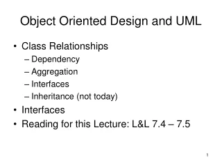
Object Modeling • Why Object Modeling? • Object Concepts • Class/Object, Attribute, Behavior, Inheritance, Encapsulation, Message, Polymorphism • Genesis of UML • UML Diagrams for Object-Oriented Analysis • Use Case Diagrams
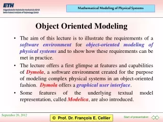
Object Modeling Object modeling is a technique for identifying objects within the systems environment and the relationships between those objects. Object-oriented analysis (OOA) techniques are used to (1) study existing objects to see if they can be reused or adapted for new uses, and (2) define new or modified objects that will be combined with existing objects into a useful business computing application. The Unified Modeling Language (UML) is a set of modeling conventions (notations) to specify or describe a software system in terms of objects.
Object Modeling • Benefits: • Break a complex system into manageable components • Create reusable components can be plugged into other systems or use them as starting points for other projects • “Object-think” is more realistic !!!
Object Concepts An object is something that is or is capable of being seen, touched, or otherwise sensed, and about which users store data and associate behavior. A class is a set of objects that share common attributes and behavior. A class is also referred to as an object class. Attributes are the data that represent characteristics of interest about an object. An instance (or object instance) of an object consists of the values for the attributes that describe a specific person, place, thing, or event.
Classes, Objects, Attributes, & Instances Customer Doe:Customer Green:Customer custNo lastName firstName phone street city state custNo:123 lastName:Doe firstName:Joe phone:1234567 street:AnyStreet city:AnyCity state:AnyState custNo:234 lastName:Green firstName:Mary phone:3456789 street:OtherStreet city:OtherCity state:OtherState changeAddress() changeAddress() changeAddress()
Object Concepts … • Behavior(method, service) refers to those activities that the object can do and which correspond to functions that act on the object’s data (or attributes). • Encapsulationis the packaging of data and method together. It shields the internal working of the object from the changes in the outside system. It keeps the system from being affected when changes are made to objects. It is the key to reusability. • All an object needs to know is the set of methods that other objects can perform and what message need to be sent to trigger them.
Common Methods • Constructor to create a new instance of a class • Query to access and get info about the state of an object but does not alter the state • Update to alter the state of an object and change the value of its attribute(s).
Supertypes & Subtypes A class supertype is an object class whose instances store attributes that are common to one or more class subtypes of the object. A class subtype is an object class whose instances inherit some common attributes from a class supertype, and then add other attributes that are unique to an instance of the subtype. Inheritance means that methods and/or attributes defined in an object class (superclass) can be inherited or reused by another object classes (subclasses).
Generalization - Specialization Employee Name DOB SSN DateHire CalSeniority() Executive Foreperson Worker Factory Station DateAppoint Wage Rate Update() Factory Station Machine Wage Rate Insert () Position Location DateAppoint Salary Update()
Object Concepts … Order Customer OrderNo OrderDate OrderStatus add() change() displayStatus() displayStatus(123) Message is the information passed when one object invokes one or more of another object's methods (behaviors) to request information or some action
Object Concepts … • Polymorphism means “many forms.” In object-oriented techniques, it means that the same message can be interpreted (and a behavior may be completed) differently by different objects/classes. • Methods of the same name in different classes. • Methods of the same name (but different parameters) in the same class • Insert(customer) is different from insert(inventory-item) as different info need to be collected and stored.
Genesis of UML • Methodological storm in object-oriented solutions (1989-94) • over 50 various object-oriented methods/solutions • Unified Modeling Language (UML) • Third generation OO method • An attempt to combine advantages of previous methods • Basis for the UML standard • Object Modeling Technique (J. Rumbaugh) – UML diagrams notation, analysis and design • Object Oriented Analysis and Design (G. Booch) – analysis and design • Object Oriented Software Engineering (I. Jacobson) – business modeling, use cases
UML Diagrams Structure diagrams. A type of diagram that depicts the elements of a specification that are irrespective of time. This includes class, object, package, composite structure diagrams and implementation diagrams: component and deployment diagrams. Behavior diagrams. A type of diagram that depicts behavioral features of a system or business process. This includes activity, state machine, and use case diagrams as well as the four interaction diagrams. Interaction diagrams. A subset of behavior diagrams which emphasize object interactions. This includes sequence, communication, interaction overview, and timing diagrams.
Most commonUML Diagrams Modeling the functions of the system (with a use case diagram). Modeling the objectswithin the scope of the system and their relationships (with class and object diagrams for each use case, and then for the integrated system). Modeling the interactions between objects to complete a function/use case (with a sequence diagram and activity diagram for each use case). Modeling the behavior / logic of the objects (with a statechart diagram for each complex class).
UML Diagrams USE CASE DIAGRAM CLASS DIAGRAM FOR USE CASE“Create New Order” Enter New Customer CUSTOMER ORDER Create New Order Order Clerk SHIPMENT :customer :order :shipment SEQUENCE DIAGRAM FOR USE CASE“Create New Order” Create Order Order Clerk Create Shipment CREATE ORDER SHIP ORDER STATECHART DIAGRAM FOR OBJECT “Order”
Use Case Modeling Use case modeling is the process of modeling a system’s functions in terms of business events, who initiated the events, and how the system responds to the events. Ause caseisa complete sequence of related actions (a scenario), both automated and manual, for the purpose of completing a business function: What the system must do. Anactorrepresents an external entity that needs to interact with the system to exchange information. An actor is a user, a role, which could be an external system as well as a person. Atemporal event is a system event that is triggered by time. (The actor of a temporal event use case istime.)
USE CASE DIAGRAM Use Case Diagram is a functional description (use cases, actors) of the entire system: functions being supported by the system Use Case Diagram does NOT indicate data flows or flows of information in and out the system (they are identified later in interaction diagrams)
Extension and Abstract Use Cases An extension use case extends the functionality of an original use case to add new behaviors or actions to the basic course. An extension use case can only be invoked by the use case it is extending. An abstract use case contains typical course steps that were common to two or more original use cases. An abstract use case reduces redundancy and promotes reuse.
Extension Use Cases(“extend” relationship) Class registration <<extend>> <<extend>> Insufficient prerequisites Registration for special classes “Class registration” is the basic course of actions. On special occasions, “Registration for special classes” and/or “Insufficient prerequisites” will be invoked. Special cases add new data/behaviors to the normal case.
Abstract Use Cases(“include” relationship) Reorder supplies <<include>> Track sales & inventory <<include>> Generate reports “Track sales & inventory” includes “Reorder Supplies” and “Generate reports”
Inheritance among Actors or Use Cases Place order by telephone Sales Representative Client Place order Place order via webpage Prepare sales report “Place order by telephone” or “Place order via webpage” are possible types of “Place order” “Sales Representative” plays all roles of “Client”
CRUD Use Cases vs. Individual Use Cases Check order status Place order DataBase Administrator Client Salesman Cancel order Administer warehouse state CRUD (Create, Read, Update, Delete) type use cases are used when application is meant to store data and one actor interacts with it (e.g. database maintenance, order management, etc.).
Use Case Documentation Each use case should include documentation in the form of scenarios Scenario is a sequence of actions documenting a behavior Each use case should have at least the main scenario but it is preferable to include the alternative scenarios as well Both main and alternative scenarios precisely describe the full functionality represented by a use case Additional important elements of the use case documentation include: pre-conditions and post-conditions
Building a Use Case Diagram Identify actors (look at the sources and destinations of major inputs and outputs) Identify use cases (major system functions) Identify the system boundary Identify associations between actors and use cases Identify additional associations between use cases (“extend”, “include”) Identify inheritance relationships among use cases and actors