Download
1 / 28
300 likes | 448 Vues
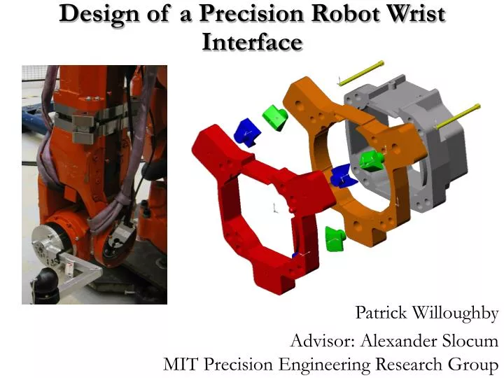
Design of a Precision Robot Wrist Interface. Patrick Willoughby Advisor: Alexander Slocum MIT Precision Engineering Research Group. Problem: Current bolted robot wrist replacements are inaccurate, causing ~1.0 mm errors at robot tool which are transmitted to the work piece.

E N D
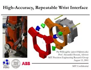
Design of a Precision Robot Wrist Interface Patrick Willoughby Advisor: Alexander SlocumMIT Precision Engineering Research Group
Problem: Current bolted robot wrist replacements are inaccurate, causing ~1.0 mm errors at robot tool which are transmitted to the work piece. Possible Solutions: Costly and lengthy calibration procedures Inexpensive classic ball and groove kinematic coupling Very inexpensive three pin coupling Project Summary
Application: ABB IRB 6400R Robot • Heavy duty industrial robot • Six degree of freedom manipulator • Carrying capacity of 200 kg • Maximum tool speed of 3 m/s • Tool position repeatability of 0.1 mm • Common applications • Automotive assembly, welding, and painting • Material Handling
Current Wrist Replacement • Requires ~½ hour to do replacement and 2 hours to perform recalibration of robot • Wrist mass of ~100kg • Replacement can cause severe damage to motor • Concerns for worker safety Robot Wrist
Existing Coupling • Uses large surface contact with alignment pins and surfaces • Repeatability is a function of machining tolerances • Repeatability of 0.3 mm • Stiffness derived from friction between interface surfaces Interface on Arm Interface on Wrist Friction Plate
Improve repeatability of wrist replacement on IRB 6400R Minimize physical changes to existing wrist structure Minimize changes in structural performance of wrist Introduce concepts of exact constraint design and kinematic couplings to ABB Strategy: Develop kinematic coupling adapter plates that can be added to robot to test repeatability Project Requirements and Strategy
Overview of Common Coupling Methods Kinematic Couplings Kinematic Constraint Elastic Averaging Non-Deterministic Pinned Joints No Unique Position Planar Kinematic Non-Deterministic
Exact Constraint or Kinematic Design • Each component has an equal number of constrained points to number of degrees of freedom • If component is over constrained, clearance and high tolerances required to prevent premature failure or assembly incompatibility • Kinematic design means that the motion is exactly constrained and geometric equations can be written to describe its motion
Ball and Groove Coupling Design • Uses standard kinematic coupling design of six point constraint in a stable coupling triangle • Preload applied through ball centers to resist static loading
Coupling Stability • Basic Definition – A stable coupling is one which remains constrained when design loads are applied • Many factors affect stability: • Geometry • Friction • Preload • Disturbance Loads
Hertz Contact Stress Design • Exact constraint design creates contact at single points or lines, creating high contact stresses • Managing Hertz contact stresses is the key to successful kinematic coupling design Contact Mechanics Equations: Equivalent radius and modulus Deflection of Contact Point Contact Pressure of Contact Ellipse c & d are diameters of ellipse
Canoe Ball and Groove Design • “Canoe Ball” Design • Places a section of a sphere with radius of 250 mm onto a small block to reduce contact stress • Large shallow Hertzian stress zone • Repeatability of ¼ micron or on the order of parts’ surface finish • Stiffness and load capacity are 100 times that of a normal 1” ball • Contact stresses determined to be 1/3 of allowable stress Units in N or N-m
CAD Model for Ball and Groove Coupling • Plates are 30mm thick • Interface plates have negative features to couple with existing interface • Interface plates installed between wrist and arm • Tabs added to outside to hold large balls and grooves, coupling features in future can be integrated into wrist Grey – Robot Structure Orange – Arm Interface Plate Green – Canoe Balls Blue – Grooves Red – Wrist Interface Plate Yellow – Preload Bolts Not Shown – Wrist Unit
CAD Model for Ball and Groove Coupling • Uses separately machined canoe balls and grooves secured to plates • Bolting Pattern • Four bolts used to secure each plate to robot structure • Four bolts to connect coupling • Three separate preload bolts • Expensive canoe features on permanent structure, cheaper grooves on “disposable” wrist • Predicted laboratory repeatability in microns
Uses a new type of coupling: Three Pin Coupling Constraint Pattern: Three Degrees of Freedom on Large Surface Contact Three Degrees of Freedom using Line Contacts on Pins In plane preload required to set coupling against friction Out of plane preload required to close interface and carry loads Planar Kinematic Coupling Design
Planar Kinematic Coupling Design Four step design process: • Determine interface geometry and method of preload. • Determine in plane preload to set coupling against interface friction using free body diagram of static load case. • Determine out of plane preload to maintain interface stiffness using free body diagram of disturbance load case. • Size pins to withstand contact and bending stresses with necessary safety factors.
CAD Model of Planar Kinematic Coupling • Plates are ~20mm thick • Interface plates have negative features to couple with existing interface • Interface plates installed between wrist and arm Grey – Upper Arm Red – Arm Interface Plate with Pins for Coupling Blue – Wrist Interface Plate with Receptacles Wrist – Not Shown
CAD Model of Planar Kinematic Coupling • All features are integral to the interface plates • Bolting Pattern • Four bolts used to secure each plate to robot structure • Four bolts to connect coupling • One in-plane preload bolt • Changes to existing robot are minimal, replace control pin and add preload pin
Operation of Planar Kinematic Coupling Pill Shaped Hole for Pin in Wrist Plate Third Pin on Arm Plate Two “Pins” on Arm Plate Preload Bolt - Steel bolt with brass tip Two “Holes” On Wrist Plate
Prototype Wrist Plate Mounting Tests at ABB Robotics Västerås, Sweden July 2001: • Tested existing coupling as well as the canoe ball and three pin wrist prototypes • Test static and dynamic (5-point path) repeatability of canoe ball • Test variety of preloads (canoe balls) • Replacement in two orientations (45 and 90 degrees to ground) • Measure tool point motion using Leica LTD500 Laser Tracker • Repeatability of robot path + measurement system approximately 20 to 30 microns
Repeatability Performance of Three Pin • Normal Wrist • 5 point measurement with 45º inclination • 5 point measurement with 90º inclination • 5 point measurement with 45º inclination Damage!! Installation Issues: • Preload could not be accurately applied as equipment was unavailable • Damage occurred to alignment features caused by wrist twisting at interface during exchange
Positions of Robot for 5pt Measurement 1 5 3 2 4
Performance of Different Coupling Designs Canoe balls vs. Normal Wrist @ 45 º = 35% reduction Canoe balls vs. Normal Wrist @ 90 º = 64% reduction Potential Three-pin vs. Normal Wrist @ 45 º = 44% reduction Performance of Different Installation Procedures for Canoe Ball Coupling Refined bolting procedure improved repeatability from 0.180 mm to 0.065 mm Mounting process at 90º improved repeatability from 0.180 mm to 0.074 mm Refined bolting procedure and mounting process at 90º improved repeatability from 0.180 mm to 0.062 mm Repeatability Results and Conclusions
Project Conclusions • Kinematic couplings can work in an industrial setting • Classic ball and groove formation requires minor modifications for space restrictions and load capacity • Three pin coupling requires further testing to verify results • Industrial applications require more attention on actual installation procedure • Some further work is required to develop a final product
Recommended Next Steps • Adapt canoe ball design to fit into space of wrist • Suggest production designs for different concepts • Investigate: • Three pin coupling in 90 degree position • Effect of friction reduction using TiN coated elements or lubrication • Coupling design independent of mounting position • Applicability quasi-kinematic couplings • Evaluate long-term dynamic performance