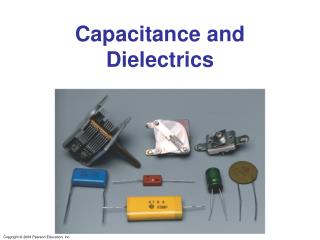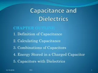
Capacitance and Dielectrics
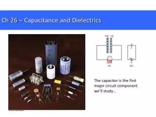
Capacitance and Dielectrics. Any two conductors separated by an insulator forms a Capacitor. Definition: 1F =1 farad = 1 C/V = 1 coulomb /volt. Capacitors and Capacitance (Chapter 24, Sec 1). Coul/m 2. Figure 24-2. Farads. 1 F = 1 x 10 -6 Farads. 1 pF = 1 x 10 -12 Farads.

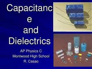
Capacitance and Dielectrics
E N D
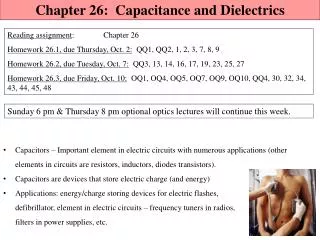
Presentation Transcript
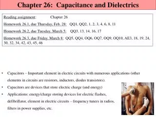
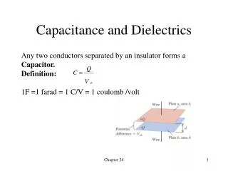
Capacitance and Dielectrics Any two conductors separated by an insulator forms a Capacitor. Definition: 1F =1 farad = 1 C/V = 1 coulomb /volt Chapter 24
Capacitors and Capacitance (Chapter 24, Sec 1) Coul/m2 Figure 24-2 Farads 1 F = 1 x 10⁻⁶ Farads 1 pF = 1 x 10-12 Farads 1 nF = 1 x 10⁻⁹ Farads Chapter 24
Useful Definitions and Relationships Chapter 24
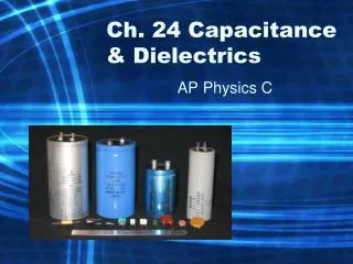
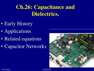
Practical Capacitors Practical Values 100µF 1µF 0.01µF 100pF 1pF Chapter 24
Some examples of flat, cylindrical, and spherical capacitors • See just how large a 1 F capacitor would be. Refer to Example 24.1. • Refer to Example 24.2 to calculate properties of a parallel-plate capacitor. • Follow Example 24.3 and Figure 24.5 to consider a spherical capacitor. • Follow Example 24.3 and Figure 24.5 to consider a cylindrical capacitor.
Capacitors in Series All capacitors in series have the same charge Q Chapter 24
Capacitors in Parallel All Capacitors in Parallel have the same voltage V Figure 24-7 Chapter 24
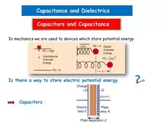
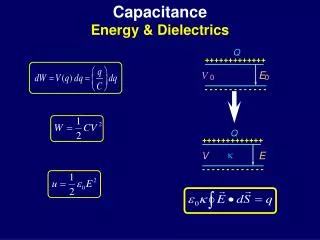
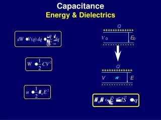
Energy Storage in Capacitors Let q equal the changing charge increasing from 0 to Q as the changing voltage v is increasing from 0 to Vab. We will determine the energy stored in the capacitor when the charge reaches Q and the voltage reaches Vab. (q and v are the intermediate charge and charging voltage joules Chapter 24
Example 24-7, Page 827 Text Transferring charge and energy between capacitors Calculate the initial charge Calculate the initial stored energy Connect the capacitors Calculate the resulting voltage Calculate the charge distribution Calculate the energy change Chapter 24
Capacitor Dielectrics Solve Three Problems Provides mechanical spacing between two large plates Increases the maximum possible potential between plates. For a given plate area the dielectric increases the capacitance. Chapter 24
Dielectrics change the potential difference • The potential between to parallel plates of a capacitor changes when the material between the plates changes. It does not matter if the plates are rolled into a tube as they are in Figure 24.13 or if they are flat as shown in Figure 24.14.
What Happens with a Dielectric A A C C0 V V0 (Q unchanged) Therefore: C C0 Figure 24-12 (Definition of Dielectric Constant) (24-12) (24-13) Chapter 24
Field lines as dielectrics change • Moving from part (a) to part (b) of Figure 24.15 shows the change induced by the dielectric.
Induced Charge and Polarization Inserting the dielectric increases permittivity by K, decreases E by 1/K and decreases energy density by 1/K The E field does work on the dielectric as it is inserted. Removing the dielectric the energy is returned to the field. Chapter 24
Dielectrics (Chapter 24, Sec 4) Induced Charge and Polarization 0 (24-15) (24-18) Therefore: E E0 Chapter 24
Dielectric Breakdown V = Ed Vmax = Emax d where Emax is the dielectric strength of the dielectric in volts/meter. For dry air: Emax = 3 x 10⁶ V/m For Mylar, K=3.1, Emax = 9.3 x 10⁶ V/m d Chapter 24
Dielectric breakdown • A very strong electrical field can exceed the strength of the dielectric to contain it. Table 24.2 at the bottom of the page lists some limits.