Download
1 / 47
940 likes | 1.79k Vues
Project presentation on OPTIMUM DESIGN OF AN ACOUSTIC ENCLOSURE FOR DIESEL GENERATOR. What is an acoustic enclosure ?. An acoustic enclosure is a containerized vessel used for housing generators to : Reduce noise levels. Improve reliability and durability of generator sets (gensets).

E N D
Project presentationonOPTIMUM DESIGN OFAN ACOUSTIC ENCLOSUREFORDIESEL GENERATOR
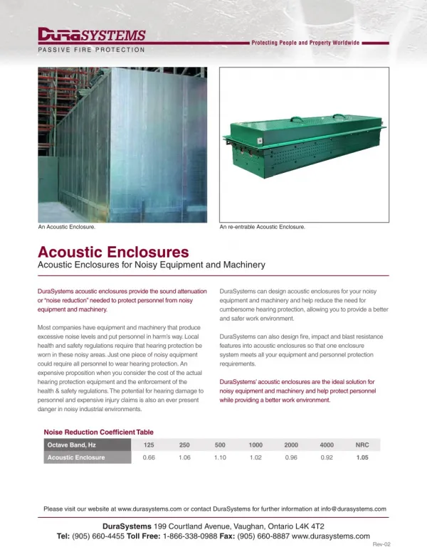
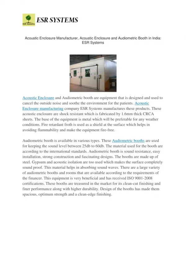
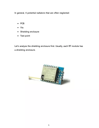
What is an acoustic enclosure ? An acoustic enclosure is a containerized vessel used for housing generators to : • Reduce noise levels. • Improve reliability and durability of generator sets (gensets). • Easy serviceability. • High uptime of genset. • Improved aesthetic of genset. • Better working conditions.
Problem statement Optimum design of an acoustic enclosure for a diesel generator set (Ratings: 125 kVA) which satisfies the following clauses: • The enclosure should act as a containerised portable vessel along with the generator set (DG set) feasible to be used for frequent mobile applications. • Proper air ventilation for DG set should be available. • Noise reduction achieved should be achieved as specified under the CPCB Norms.
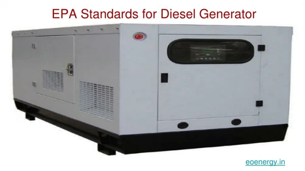
Design data specifications: • Genset model : Cummins DB 125 (diesel) • Genset rating : 125kVA • Current (Amp) : 179 • Fuel consumption: 149 gm/kW-hr • Length (mm) : 2225 • Width (mm) : 925 • Height (mm) : 1600 • Weight (Kg) : 1370 • Engine BHP : 154 • No.of cylinders : 6 • RPM : 1500 • Cooling : Water cooled
Presentation details Introduction Problem definition Resultcomparison Structuredesign Airventilation Soundproofing Futurescope References
NEED FOR STRUCTURE DESIGN • Preventing escape of sound to surrounding • Earlier enclosure has to be installed on site around the fixed generator • Now a days enclosure are made such that they contain the generator inside • Thus can be moved as a single unit • To optimize proper lifting points • Selection of proper beams and columns
DESIGN PROCEDURE MATERIAL SELECTION FOR FRAME SELECTION OF IDEAL C/S FOR CHANNELS CREATING FEM MODEL OF ENCLOSURE FRAMEWORK OPTIMIZATION PROCESS CHANNEL DIMENSION SELECTION ENCLOSURE LIFTING NODES
Raw material selection • Material selection initially can be arbitrary. • For acoustic enclosures, as per design analysis, the material selected should be such that it has: . Good strength and rigidity preventing failures lifting, transporting, and working conditions. . Ease of manufacturability (fabrication, assembly) . Structural reliability for a prolonged life with minimum maintenance cost . Structural compliance with IS standards (including safety regulations, FOS, Pollution norms) STEELS , preferably heat treated steel AISI1020is used for rigid structures because of their good strength, ductility, availability, weld ability and highest scrap value.
Selection of frame columns & beams • Columns and beams are selected based upon their cross-sections. • By using identical dimensions for different cross-sectional columns or beams like I-section, L-section and []- section, the one with better strength can be selected • Material is same ,therefore bending stresses are assumed to be same • Using the formula: Strength (M) = bending stress (P) * section modulus (Z) • Thus strength is directly proportional to section modulusand the section with greater value of Z is selected. • Hollow rectangular channel gives the better strength
Material selected is AISI 1020 • Selecting ideal C/S of channels : • Moment of resistance (strength) M = σb * Z = σb * (I/y) • Consider various shapes of channel to calculate m.o.i : • For hollow rectangular section, I = (BD3/12) – (bd3/12) = ((100*1803)/12) – ((92*1723)/12) = 95.8 * 105 mm4
For I section, Ixx = ((B*D3)/12)-((b*d3)/12) = ((100*1803)-(92*1803))/12 = 48600000-44712000 = 38.8*105 mm2 • For C channel, By area method, Co-ordinates for centroid of section X = 25248/2112 = 11.95 Y = 90 So, I = 59.68*105 mm4
FINITE ELEMENT METHOD • ANSYS 10 is used • Model created in ANSYS (fig showing structure model using BEAM44 of hollow rectangular C/S)
METHODOLOGY OF FEA • Discretize the continuum • Select interpolation function • Find the element properties • Assemble the element properties to obtain the system equations • Impose the boundary conditions • Solve the system equations
Taking the genset load at predefined nodes and lifting supports at 4 end nodes of enclosure we can analyze the system for maximum and minimum stresses as follows:
OPTIMIZATION PROCESS • The sub-problem approximation method is used • Max allowable stress is 84 MPa • Maximum feasible and infeasible sets for iteration are chosen 100 and 80 respectively • Quadratic curve fitting polynomial function is chosen for design and state variables for next iteration • Design variable: 5 ≤ t ≤ 12.2 0 ≤ LOCX1 ≤ 2000 • State variable: 10 ≤ MAXSTRESS ≤ 84 • Objective function: weight=dens *(2*B*t+2*(D- 2*t)*t*(4000*4+1600*6+2000*4)) • Where, dens =density of AISI 1020 i.e. 7850 kg/m3
From above analysis we obtain maximum stress in the entire structure as 53.511 MPa and the feasible nodes are for lifting are at a distance 482 mm from all base nodes. The optimum thickness value obtained is 6.2 mm. The analysed result obtained can be formulated on graph as follows: Design Optimization
FEA of Final Optimization Result of channel selection 127 x 64 RSC (failed) FEA of Final Optimization Result of channel selection 152 x 76 RSC (correct)
The optimum channel selection is 152 x 76 RSC of material AISI 1020 Graph for optimized result
Cross ventilation and fresh air is must for satisfactory operation of genset. Air should flow from alternator to engine end. As air flows through enclosure, its temperature increases. This increase is difference between temperature measured at alternator and at outdoor. The maximum allowed temperature rise is limited to 5oC to 10oC.
The Required air flow rate to keep specific temperature rise in control can be calculated as : ma = where, ma= mass flow rate of air into enclosure Q = heat rejection into enclosure (25kW) Cp=specific heat (0.017 kW/˚C) ∆T= temperature rise in enclosure (5 ˚C) ρ= density of air (1.099 kg/m3)
So, for ∆T=5 o C, we require mass flow rate of air of about 4469.30 lit/sec. To allow this air flow in the enclosure, we need proper inlet and outlet openings without any compensation in soundproofing. Also, care has to be taken that, at high velocities of radiator fan, there should be no suction of rain water, dirt, debris or any other unwanted elements with the air . To achieve such opening, which allows only air to pass with minimum foreign particles ‘LOUVERS’ are used.
A louveris a ventilation product that allows air to pass through it while keeping out unwanted elements The basic consideration for louver section are :- • Free Area • Water penetration • Resistance to air flow Fig.- Louver
Free area is derived by taking the total open area of a louver and dividing by the overall wall opening. Generally, it is taken as 35% to 60%. First Point of Water Penetration is the point at which a louver allows the passage of water through the louver. Fig.- Free Area for Air Flow Fig. Good Water Resistance Louver
Every obstruction in the airstream creates resistance, which reduces velocity of air flow.The resistance of the louver can be measured by running air through the louver and measuring the pressure differential at various free area velocities.Lower blade angles or more aerodynamic shapes create less resistance. Fig. - Resistance to Air Flow
For proper enclosure ventilation our objective is to select louver dimensions for both inlet and exit keeping in mind : • The company standards • Prescribed static pressure • Louver considerations Fig.- Path of Air Flow through Louver
Selection of louver material Apart from steel most commonly used louver material today is the aluminium AISI 6063 T5 because of the following reasons: • Light weight construction. • Feasible mounting for various opening types. • Architectural surface finishes provides minimum drag against air flow. • It can sustain higher wind loads of up to 100mph. • Able to withstand high temperatures of air about 600 to 650˚C.
Calculation procedure Find louver free area Refer company standards and free area chart to get louver dimensions Find front inlet louver dimensions (1.5times the radiator core ) Find rear exit louver dimensions (2.5 to 3 times the radiator core) Check for back pressure < 6mm of water column Opening for inlet is done on either sides of enclosure as shown in the diagram Obtain final louver dimensions
TARGET • Reduce the maximum sound power level of 97dB to 71 dB at distance of 1 meterfrom all sides of enclosure.
NOISE PREDICTION METHOD (theoretical) • This method can predict level of noise with acceptable engineering accuracy over the frequency range 50-5,000 Hz using simple and readily available expressions. • According to experiments performed by National Research Council (NRC) in Canada the difference between practical measurement and theoretical noise prediction is less than 0.5dB and 90% of results were found to lie within ± 2.5 dB.
CONCEPT AND FORMULA USED Formulae used: L = Lρ – TL + 10Log(S/A) – 20Log(r) – 8.......................1) TL = 20 Log (n*t*freq) - 47............................................... 2) A = α · S ...........................................................................3)
F L O W C H A R T
ADVANTAGE & LIMITATION • This method uses the design data about a newly developed enclosure to simulate its noise. • Frequency range is taken into consideration. • Ease of use. • Accuracy of method is less as it does not taking into account the Insertion losses(IL) & only consider transmission losses(TL). Insertion loss models are still under research.
CONSIDERED WITH STEEL &ALUMINIUM PLATE d) Rockwool ( Density = 36.84kg/m3) e) Steel plate (Density = 7850kg/m3) f) Aluminium plate (Density = 2700kg/m3) a)Polyethylene foam ( Density = 36.84kg/m3) b) Armaflex foam (Density = 40.045 kg/m3) c) Coir fibre foam (Density = 74 kg/m3)
Future scope Study and development of optimization code by combining the following aspects for acoustic enclosure: • Optimum Weld thickness to be used • Computational fluid dynamics of flow of air through enclosure • Thermo-structural analysis to study effective heat transfer around the DG set in the enclosure • Development of insertion loss model for acoustical treatment at the sound source. At present transmission losses of 25 dB have been achieved from the various acoustical materials applied to the enclosure body. But, additional sound reduction of up to 10 dB can be achieved using insertion loss phenomenon.
REFERENCES: BOOKS • Mechanical Engineering Design, by Joseph E. Shingley, Pg. 933, 983. • Design of Machine Elements, by V. B. Bhandari, Pg. 1 to 82, 22 to 57, 71 to 85. • Structural Design and Drawing, by N. Krishna Raju, Pg. 199 to 203. • Structural Engineering for Architecture, by A. P. Dongre, Pg. 13.1 to 13.8. • Statics and Strength of Material (Foundation for Structural Design), by Barry Onouye, Pg. 151to 261, 415. • Mechanical Vibrations and Noise Engineering, by A. G. Ambekar, Pg. 343 to 384. JOURNALS • Diesel Engines Technical Data, published on Aug 1998(Company Confidential). • Reciprocating internal Combustion Engines (British Standard Controlled). • Application Manual-Liquid Cooled Generator Sets (Company Confidential). • Engine Installation Recommendation (Company Confidential). • Genset Installation Recommendation (Company Confidential).
PAPERS • Optimal Design of an Enclosure for a Portable Generator, by • Joseph E. Blanks. • Development of Technique to Predict Level of Dynamic Noise of Hydraulic Excavators, by Mikio Iwasaki. • Accuracy of Prediction Methods for Sound Transmission Loss, by K. O. Ballagh. SITES • http://www.efunda.com/Materials/Alloys/carbon_steels/ show_carbon.cfm?ID=AISI_1020&prop=all&Page_Title=AISI%201020. • http://www.conpargroup.co.uk/evenchan.htm • http://www.engineersedge.com/beam_bending/beam_bending5.htm • http://www.sail.co.in • info@structural-world.org