Download
1 / 16
160 likes | 173 Vues
This project aims to upgrade the muon detectors in the CMS experiment at CERN using GE1/1 GEM technology. The upgrade will ensure efficient trigger coverage and reconstruction in high background environments. The plan includes the installation of GE2/1 GEM technology in LS2 and the development of new front-end electronics.

E N D
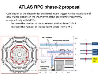
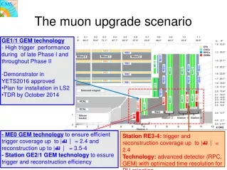
The muon upgrade scenario • GE1/1 GEM technology • - High trigger performance during of late Phase I and throughout Phase II • -Demonstrator in YETS2016 approved • Plan for installation in LS2 • TDR by October 2014 - ME0 GEM technology to ensure efficient trigger coverage up to | = 2.4 and reconstruction up to |= 3.5-4 - Station GE2/1 GEM technology to essure trigger and reconstruction efficiency Station RE3-4: trigger and reconstruction coverage up to | = 2.4 Technology: advanced detector (RPC, GEM) with optimized time resolution for PU rejection
GEM Upgrade Projects GE2/1 • GE1/1: baseline detector for GEM project • 1.55 < |eta| < 2.18 • Guarantee high trigger performance during late Phase I • and throughout Phase II • -Demonstrator in YETS2016 approved • Plan for installation in LS2 • GE2/1: station 2 • 1.55 < |eta| < 2.45 • - Station GE2/1 GEM technology to ensure trigger and reconstruction efficiency • ME0: near-tagger to be installed behind new HE • 2.0 < |eta| < 3.5 • 6-layers of triple-GEM detectors • Ensure efficient trigger coverage up to | = 2.4 and reconstruction up to |= 3.5-4 in very high background environment GE1/1 ME0 Simulation ready in CMSSW
GEM R&D 2013/14 2010 2011 2012 2013 Generation I The first 1m-class detector ever built but still with spacer ribs and only 8 sectors total. Ref.: 2010 IEEE (also RD51-Note-2010-005) Generation II First large detector with 24 readout sectors (3x8) and 3/1/2/1 gaps but still with spacers and all glued. Ref.: 2011 IEEE. Also RD51-Note-2011-013. Generation III The first sans-spacer detector, but with the outer frame still glued to the drift. Ref.: 2012 IEEE N14-137. Generation IV The current generation that we have built two of at CERN so far, with four more to come from the different sites. No more gluing whatsoever. Upcoming papers from MPGD 2013; And IEEE2013. Generation V The upcoming detector version that we will install. One long and one short version. Optimized final dimensions for max. acceptance and final eta segmentation. Installation of dummy chambers GEM foils production Single mask technology etching. Effects dramatically on foils production costs. Same performance of double mask New Front-end electronics development
Performance Detector efficiencies ~98% Time resolution ~4ns Spatial resolution of about 290μm with VFAT2 (digital) and <110μm APV (analog) readout chip Operation of GEMs in magnetic field Gas mixture Ar/CO2/CF4 (45/15/40) Rate capability ~105Hz/cm2 Good performance in test-beams at CERN SPS and FNAL Technology and assembly Validation of single-mask technology Production of large area GEM foils (GE1/1-type) NS2 technique for GEM assembly Integration Dummy GEMs for trial installation GEM project achievements
Step 1: preparation of drift board Equip PCB with metallic inserts and HV probes Fix outer frame to PCB with guiding pins Step 2: preparation of GEM stack Place 1st frame on support Place GEM1 + second frame Place GEM2 + 3rd frame Insert stretching nuts Place GEM3 + 4th frame Step 3: installation and stretching Remove the guiding pins Place stack on drift plane Check electrical contacts & HV divider Close chamber with readout PCB Insert gas in- and outlets GE1/1 chamberconstruction • Only 2 hours to assemble the full-scale GE1/1 • (Compared to >2 days for the triple-GEM without NS2) • 6 GE1/1-IV types have been built at various sites: • Bari, LNF, CERN, FIT, Ugent,
Ongoing investigations at P5 by technical crew Optimize cable and fibre routing, and layout of cooling pipes Racks for electronics equipment and powering (HV/LV) GE1/1 super chamber dummies produced (May 2013) 1st trial installation in Summer 2013 New dummies according to updated geometry (Jan 2014) 2nd trial installation in March 2014 Integration into CMS Disassembled GE1/1 dummies YE1/1 nose Assembled GE1/1 dummies Available space for GE1/1 Dummies with short and long chambers
Bari Lab for GEM chamber characterization and construction: Acquisition chain (FEE, DAQ, cosmic telescope, gas system for ternary mixtures) Set of measurements in progress: Charge, timing, gas mixtures study Custom electronic tool developed for GEM foils and readout plane QC Present on-site infrastructures (clean room equipped for GEM construction and X-ray facility under preparation for gain uniformity study) Bari R&D Activities
One GEM based 10x10 cm2 detector built and under characterization readout by a board based on the GASTONE chip for a total of 128 channels Anodic readout planes custom designed for spatial resolution study Measurements with different gas mixtures Freon-free are foreseen and in progress GEM1/1_IV prototype built and under characterization Bari R&D Activities Cs137 and Fe55 irradiation source measurements for gain and gas mixtures test
The GEM power system will provide high and low voltages to the 144 GEM chambers and to the front-end electronics boards. The design of the power system is strongly related to the chamber design and to the grounding schema of the full system. Custom solutions have been adopted by KLOE and LHCb. Commercial solution are available. Pierluigi Paolucci - INFN of Napoli Napoli R&D Activities GE1/1 Power system
LNF R&D Activities • Safe operation of GEM detector made of composite materials • Over 20 yrs, in harsh hirad envronm, eco-friendly • Develop simple, cost-effective, mass production tool to assess GEM foils’ planarity and parallelism within 100um over the 1mm gap • Thus addressing a specific question by Apollinari review committee • Discover if an in situ monitoring of stretching and planarity is possible • Characterization of materials pre- and post- irradiation • Kapton, glue, etc • New eco-gas • Characterize stretching of GEMs, develop optical Moire’-based techniques • Install optical sensors permanently on GEM chambers ? CHALLENGES SOLUTIONS R&D Materials and Stretching of GEMS (I) L.BenussiS.BiancoM.CaponeroM.FerriniL.PassamontiD.PiccoloD.PierluigiG.RaffoneA.RussoG.Saviano
LNF R&D Activities R&D Materials and Stretching of GEMS (I) L.Benussi S.Bianco M.Caponero M.Ferrini L.Passamonti D.Piccolo D.Pierluigi G.Raffone A.Russo G.Saviano DGEM=(3.3 ± 0.1)10-‐10 cm2/s Preliminary R&D results G.Saviano et al. Study of GEM film and foil materials… SIENA 2013, accepted by JINST V.A.Franchi et al., Measurement of Diffusion coefficient…, INFN-13-09/LNF G.Raffone, CHE and related stress in GEM foils, INFN-13.11/LNF G.Raffone, , CMS trapezoidal GEM foil stuctural analysis, INFN-10/20(IR) MOIRE’ FRINGES SENSITIVE TO 100um, EXPECT MUCH BETTER WITH PHASE-SHIFT 100um 300um FULL SCALE MOIRE’ GEM CHAMBER HERE ECO-GAS CHARACTERIZATION WITH GASCROMATOGRAPH
Pierluigi Paolucci - INFN of Napoli Napoli R&D Activities • General requirements: • working in high magnetic field(up to 2 Tesla); • working in an high radiation environment • (5*1010p/cm2& 5*1011n/cm2 & 12-15 kRad); • local system in control room + distributed remote systems on the detector (at least for the LV); • redundancy of the control electronic devices (mP per board) • input voltage from the CMS AC/DC 48V power supply; • Floating channels up to 5 V each other • looking forward common CMS solutions in order to simplify the hardware and software development/maintenance of the systems
The main requirements of the GEM power system are: assure a very high stability of the detector low noise induced on the chamber and front-end electronic (floating channels + filters) Reduced number of cables to run out from the chamber HV range 4-5 KV with 1 mA per chamber !!! compatible with CMS DCS and DSS system be modular and accessible and have a reasonable cost. Pierluigi Paolucci - INFN of Napoli Napoli R&D Activities GEM detector Requirements
Napoli R&D Activities HV schema - proposal HV Distributor + filter * Any resistor along the HV line introduce a Voltage drop. PS system • CAEN EASY PS and is under test in Napoli • A first passive filter* will be introduced on the HV board or on the distributor • A second and most important passive filter* will be mounted as close as possible to the chamber. This can be also used to protect the chamber from spikes. • Test at CERN or LNF will be done in the first part of the 2014. • Cables routing on the chamber is under study in Napoli. GEM 1 filter HV D I v i d e r GEM 2 filter GEM n filter