Download

1 / 27
270 likes | 303 Vues
Explore layered manufacturing technologies to speed up production processes and conserve material. Learn about QuickSlice software, Fast Build limitations, and innovative strategies like 3D Offset Pipeline. Discover how to implement 2D contour offsetting and benefit from regularized boolean operations.

E N D
Layered Manufacturing of Thin-Walled Parts Sara McMains, Jordan Smith, Jianlin Wang, Carlo Séquin UC Berkeley
3.5”, 20hrs 2.5”, 15hrs 3.0”, 25 hrs Is Layered Manufacturing really Rapid Prototyping? • How can we speed up these manufacturing technologies?
Raster Scan Technologies • Example: 3D Printing • Speed of roller limits the process • Build time =z-height • Speed up: pack build volume in xy with many parts
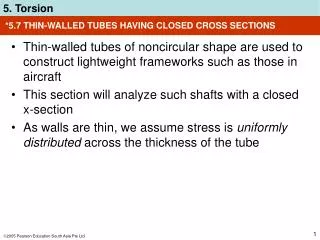
Vector Scan Technologies • Example: FDM (Fused Deposition Modeling) • Build time = volume scanned (material used) • Our Goal: create a sturdy part that is visually equivalent but uses less material, so that it builds faster
QuickSlice FDM 3D B-Rep STL SSL SML Slicer Support Roads Building Solid Parts with QuickSlice • Software interface to Stratasys 1650 FDM Machine • Input: STL boundary representation • Slices model into z-layer contours (SSL) • Builds support structure • Builds roads (nozzle fill path) (SML)
QuickSlice Fast Build QuickSlice FDM 3D B-Rep SML STL SSL Slicer Support Fast Roads • Builds a semi-hollow version of the solid • n solid offset rings • Center filled with a loose crosshatch pattern
z Fast Build Limitations • Structurally conservative • Only applied to slice layers whose center area is completely covered by slices above and below it • Gradually sloping surfaces prevent its application • Worst case example
Can Approach Be More Aggressive? FDM 3D B-Rep Automated Process? SML • Our Goal: • Create an automated process • Input: the boundary representation of a desired solid geometry • Output: a sturdy, physical part that is visually equivalent while using less material • Benefits: faster build times and material conservation • Our Assets: • QuickSlice software as a black box • Specifically the loose fill crosshatched roads option
z Idea #1: 3D Offset Pipeline FDM 3D B-Rep Polyhedron Offset STL Quick Slice SML • Solid-fill the volume between the input and the offset surfaces • Crosshatch-fill the volume within the offset surface Assume we have true 3D offset surface at the desired distance inward Unfortunately, the 3D offset is difficult to implement robustly!
Idea #2: Approximate 3D Offset QuickSlice FDM 3D B-Rep Slices Slicer SSL SML Slicer Support Roads • Key ideas: • Offsetting is much simpler in 2D than in 3D • The manufacturing process eventually represents the part as a stack in z of layers of 2D contours • Start: slice polyhedron into desired set of 2D contours • End: input SSL to QuickSlice to build support and roads
2D Contour Offset FDM 3D B-Rep QuickSlice Slices Offsets Slicer Contour Offset SML S S R • Data: layers of 2D contours • Offset the 2D contours inward by a specified distance = n layer thicknesses • Near vertical walls, this is the correct 3D offset • Approximation degrades as the walls approach horizontal SSL
2½D Polyhedron Offset FDM 3D B-Rep QuickSlice Slices Offsets Slicer Contour Offset 2½D CSG SML S S R • Data: layers of 2D contours and offsets • Adjust the loose fill areas in regions where the vertical coverage above or below is less than n layers thick • Perform 2D boolean (CSG) combinations of the contours and offsets of the ith layer with the n layers above and below it • We use OpenGL for the 2D booleans SSL
Regularized Boolean Operations • Unregularized:op { , , - } • Regularized:op* { *, *, -* } • A op* B = Closure( Interior( A op B ) ) • If A & B are 2D areas and C = A op* B then C is a non-degenerate 2D area or A B A B A * B
z 1-Layer Thick 2½D Offset
z 1-Layer Thick 2½D Offset
z 1-Layer Thick 2½D Offset
z n-Layer Thick 2½D Offset
z n-Layer Thick 2½D Offset
z n-Layer Thick 2½D Offset
QuickSlice Fast Build Time: 504 min (8:24) Filament used: 22.1 m 2½D Offset Method Time: 232 min (3:52) Filament used: 7.6 m Results: the Bolt Part QuickSlice took 2.71 times as long and used 2.9 times as much filament
Conclusion • We have implemented a robust 2D contour offsetting program. • We have conservatively approximated the 3D polyhedron offset using 2D contour slices, 2D offsets, and 2½D boolean operations. • We have demonstrated a novel approach to speeding up FDM manufacturing. • Our approach decomposes the desired geometry into a thin sturdy outer shell with a loosely filled center volume. • Our approach saves time and material as compared to the built-in QuickSlice solution.
Thanks to our Sponsors • NSF • CyberCut • CADRE: • MOSIS++: A Distributed Manufacturing Resource (EIA-9905140) • Ford Motor Co.
2D Contour Offset Implementation Input Offset 0.1 Offset 0.2 • Difficulties arise from global interactions • Robust approach based on Voronoi diagram • Generalization of the approach described by M. Held 1991
Voronoi Diagram of a Contour • Input sites are both Vertices and directed Edge Segments • VD divides the plane into zones s.t. every point in a zone is closest to the corresponding input site than to any other site • Vertices of VD have an associated signed distance • VD is a signed distance function
z Voronoi Mountain z = 0 • Create a height field by raising the vertices of VD in z by their signed distance • Offsetting by n is the same as slicing the mountain with the plane z = n
Offset Slicing z-monotone parabolic VD edges for each unvisited VD edge if VD edge z = n Crawl VD CCW around peak CW around each VD face
Dragon Curve Example Input Voronoi Diagram Offset