Download
1 / 23
230 likes | 334 Vues
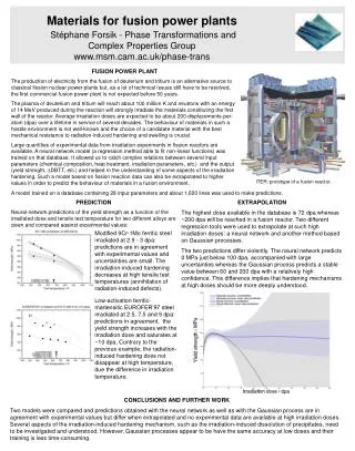
This paper discusses the impact of different materials as liners for a neutron trap, focusing on reducing neutron and gamma flux. Results show the effectiveness of boron-rich materials in improving optics lifetime. Detailed 2-D neutronics analysis was conducted to compare various liner options. Lightweight GIMM design configurations were evaluated to optimize radiation environment at the dielectric mirror. The study concludes that boron-based materials have the best effects on flux reduction, with Boron Hydride and Borated Polyethylene being particularly efficient. The findings provide insights into enhancing the performance and longevity of optics in fusion technologies.

E N D
Nuclear Assessment for Final Optics of HAPL Mohamed SawanFusion Technology InstituteUniversity of Wisconsin, Madison, WIWith contribution fromAhmad Ibrahim (UW)HAPL MeetingGA, San Diego, CAAugust 8-9, 2006
Design Parameters for Baseline HAPL Design Target yield 367.1 MJ Rep Rate 5 Hz Fusion power1836 MW Chamber inner radius 10.75 m Thickness of Li/FS blanket 0.6 m Thickness of SS/B4C/He shield 0.5 m Chamber outer radius 11.85 m NWL @ FW 0.94 MW/m2 GIMM angle of incidence85° GIMM distance from target24 m
Energy Spectra of Source Neutrons and Gammas Used in Neutronics Calculations
R (m) Shield Blanket Neutron Trap 2 GIMM Z (m) 10 24 40 Impact of Liner Material on Reflection from Neutron Trap • Investigated effectiveness of lining inner surface of neutron trap on reflection • Effect investigated with a transparent GIMM with all source neutrons impinging on the lined trap • Flux calculated at 40 cm from bottom of trap • Liners considered are: • Boral (Al+B4C) • Borated Polyethylene • WC • Boron Hydride (B10H14) • Option of adding boron to the concrete shield was also investigated
Impact of Liner Material on Reflection from Neutron Trap • Boron is more effective in reducing the low energy component of the neutron flux with modest effect on fast neutron flux and gamma flux increases • Heavy material like WC is effective only in reducing gamma flux • Materials rich in hydrogen and boron (boron hydride, borated polyethelyne) have the best impact on fast neutron flux that is believed to impact optics lifetime
Baseline HAPL Optics Configuration with GIMM Provided by Malcolm McGeoch
Detailed 2-D Neutronics Analysis • 2-D neutronics calculation performed in R-Z geometry to compare the impact of the GIMM design option and duct lining on the radiation environment at the dielectric mirror • Two lightweight GIMM design options were considered • Z axis is along the beam line • Due to 2-D modeling limitation, circular GIMM, beam port, and neutron trap were used with the area of beam port preserved • Beam port at chamber wall is 0.23 m high x 1.38 m wide modeled as circular port with 0.225 m radius • GIMM modeled circular with 0.45 m radius • Neutron traps used behind GIMM and M2 • Effective thickness of GIMM layers as seen by source neutrons was modeled (effective thickness = actual thickness/cos85) • Detailed layered radial build of blanket/shield included in model • Containment building housing the optics and neutron traps used with 70% concrete, 20% carbon steel C1020, and 10% H2O
M3 GIMM Vertical Cross Section in the 2-D Neutronics Model M2
Isometric View of the 2-D Neutronics Model M3 VV/Shield Concrete Shield Blanket M2 GIMM Beam Duct
Impact of Liner Material on Radiation Level at M2 • Boron hydride and borated polyethelyne have the best impact on fast neutron flux that is believed to impact optics lifetime • However, effect at M2 is very small since flux is dominated by direct neutrons scattered from GIMM with smaller contribution from neutrons scattered from duct wall • Design complexity from adding liner is not justified
Impact of Liner Material on Radiation Level at M3 • Effect of liner enhanced at M3 • Boron hydride and borated polyethelyne have the best impact on fast neutron flux that is believed to impact optics lifetime • However, effect at M3 is at most a factor of 2 reduction • Since flux at M3 is much smaller than that at M2, design complexity from adding liner is not justified
GIMM Design Options for HAPL • Two options considered for GIMM materials and thicknesses • Both options have 50 microns thick Al coating • Option 1: Lightweight SiC substrate • The substrate consists of two SiC face plates surrounding a SiC foam with 12.5% density factor • The foam is actively cooled with slow-flowing He gas • Total thickness is 1/2" • Total areal density is 12 kg/m2 • Option 2: Lightweight AlBeMet substrate • The substrate consists of two AlBeMet162 (62 wt.%Be) face plates surrounding a AlBeMet foam(or honeycomb) with 12.5% density factor • The foam is actively cooled with slow-flowing He gas • Total thickness is 1" • Total areal density is 16 kg/m2
M3 M2 GIMM Fast neutron Flux Along Beam Line • Neutron flux is higher by a factor of ~2 with AlBeMet GIMM due to larger thickness and neutron multiplication in Be • Significant drop in flux occurs at beam duct bend around location of M2 • Peak fast neutron flux at M3 is ~2 orders of magnitude lower than that at M2
M3 M2 GIMM Gamma Flux Along Beam Line • Gamma flux is comparable up to M2 due to dominant contribution from GIMM but is higher at M3 with AlBeMet GIMM due to dominant contribution from gamma generated in shield by the larger neutron flux • Significant drop in flux occurs at beam duct bend around location of M2 • Peak gamma flux at M3 is ~ an order of magnitude lower than that at M2
M3 M2 GIMM Neutron Spectrum Along Beam Line • Neutron spectrum gets harder in part of beam duct approaching M2 (not in direct view of GIMM neutron trap) with more direct contribution from GIMM and less from trap • Neutron spectrum softens significantly at M3 • Neutron spectrum is slightly harder with SiC GIMM
Flux at Front of GIMM • Contribution to neutron flux at GIMM from scattering inside chamber is small (<3%) • Up to 37% of fast neutron flux contributed from scattering in GIMM itself • Material choice and thickness impact peak flux in GIMM • Neutron flux is higher for AlBeMet (due to Be(n,2n)) and gamma flux is higher for SiC (due to Si inelastic scattering) • Neutron spectrum softer for AlBeMet with 86% >0.1 MeV compared to 95% for SiC
Nuclear Heating in GIMM • Values are at center of GIMM @ 24 m from target and variation along the 5.2 m length of GIMM scales as 1/R2 • Power densities in face plates are comparable for the two designs but contribution from gamma heating is smaller in the AlBeMet design • Nuclear heating in GIMM increased by 30-40% when imbedded in concrete shield • For 1.2 mm thick SiC face plate nuclear heating is 82 mW/cm2 • For the twice thicker AlBeMet face plate nuclear heating is 132 mW/cm2 • This is compared to the heat flux from laser (22 mW/cm2) and x-rays (23 mW/cm2)
Flux at Focusing Dielectric Mirror M2 Located @14.9 m from GIMM • Neutron flux is about a factor of 2 higher with AlBeMet GIMM • Total neutron and gamma fluxes are more than two orders of magnitude lower than at GIMM • Neutron spectrum is hard with ~85% of neutrons @ E>0.1 MeV and ~70% of neutrons @ E>1 MeV • Gamma flux is comparable for two GIMM cases
Flux at Plane Dielectric Turning Mirror M3 Located @ 1.6-6 m from M2 • Neutron and gamma fluxes are about a factor of 2 higher with AlBeMet GIMM • Total neutron flux is more than two orders of magnitude lower than at M2 with smaller gamma flux reduction • Neutron spectrum is softer with ~30% of neutrons @ E>0.1 MeV and ~15% of neutrons @ E>1 MeV
Nuclear Heating in Sapphire M2 and M3 Mirrors • Nuclear heating in M2 is more than 2 orders of magnitude lower than in the GIMM • Peak nuclear heating in M3 is about 2 orders of magnitude lower than in M2 • Nuclear heating in the dielectric mirrors are a factor of 2 higher with AlBeMet GIMM compared to that with SiC GIMM
Started Modeling Final Optics for Detailed 3-D Analysis with MCNP-CGM • Modeled one duct with reflecting boundaries • All 3 mirrors and accurate duct shape included
Started Modeling Final Optics for Detailed 3-D Analysis with MCNP-CGM • Modeled one duct with reflecting boundaries • All 3 mirrors and accurate duct shape included
Summary and Conclusions • 2-D neutronics calculation performed to compare impact of GIMM design option and duct lining on the radiation environment at the dielectric mirrors • Lining beam ducts with materials rich in hydrogen and boron (boron hydride, borated polyethelyne) have best impact on fast neutron flux • Effect is small (<4%) at M2 but up to a factor of 2 reduction at M3 • Since flux at M3 is much smaller than at M2, design complexity from adding liner is not justified • Neutron flux at GIMM is higher for AlBeMet and gamma flux is higher for SiC • Neutron flux at dielectric mirrors is higher by a factor of ~2 with AlBeMet GIMM due to larger thickness and neutron multiplication in Be • Peak fast neutron flux at M3 is ~2 orders of magnitude lower than at M2 • Neutron spectrum softens significantly at M3 (~25% >0.1 MeV) compared to ~85% at M2 • Peak fast (E>0.1 MeV) neutron fluence per FPY: • GIMM 4.9x10²⁰ n/cm2s • M2 1.92x10¹⁸ n/cm2s • M31.34x1016 n/cm2s • Model for 3-D neutronics of final optics