Reflected Solar Calibration Demonstration System - SOLARIS
250 likes | 434 Vues
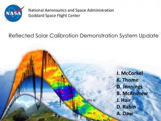
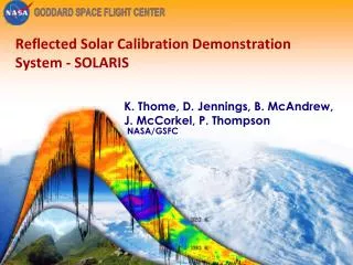
Reflected Solar Calibration Demonstration System - SOLARIS. K. Thome, D. Jennings, B . McAndrew , J . McCorkel , P. Thompson. NASA/GSFC. Calibration Demonstrator System. SOlar , Lunar for Absolute Reflectance Imaging Spectroradiometer (SOLARIS) Technology demonstration of

Reflected Solar Calibration Demonstration System - SOLARIS
E N D
Presentation Transcript
Reflected Solar Calibration Demonstration System - SOLARIS K. Thome, D. Jennings, B. McAndrew, J. McCorkel, P. Thompson NASA/GSFC
Calibration Demonstrator System • SOlar, Lunar for Absolute Reflectance Imaging Spectroradiometer (SOLARIS) • Technology demonstration of • Design and production of optics • Depolarizer technology • Test prelaunch calibration methods • Evaluate reflectance retrieval • Demonstrate transfer-to-orbit error budget showing SI-traceability
CDS – Overall goals Calibration demonstrator provides tests of laboratory characterization approaches Robust, portable tunable-laser facility including transfer radiometers with sufficient spectral coverage Broadband stray light and polarization systems of sufficient fidelity Depolarizer technology Thermal control of attenuators and detector needs to be proven Development of physically-based spectrometer models including well-understood error budgets
CDS – Reflectance retrieval Retrieve reflectance by taking the ratio of the solar irradiance and the signal from the scene Instrument model development for stray light and other geometric effects Correction techniques for solar attenuators Validation of reflectance done in laboratory & field Currently available laboratory equipment Compare with state-of-the art field approaches Observations of sun and moon CDS will provide check on instrument models and reflectance retrieval approaches
CDS – SI traceability and transfer to orbit Path to SI traceability (source and detector standards) Verifiable error budgets Instrument model development and evaluation Develop and check calibration protocols and methods
Key error terms Key uncertainties are Geometry differences between the solar and earth views Knowledge of attenuator behavior when viewing sun Sensor behavior • Detector linearity • Noise behavior Polarization Developed a preliminary error budget based on a nominal design for the RS sensor
1st Image through entire system Line source illumination to evaluate spectral characteristics of system October 2011 Complete optical package coupled with COTS detector Better spatial resolution Allowed SOLARIS detector development to continue in parallel Interferometric tests of full optical system also took place Results match well with predicted performance “Snap” together approach worked extremely well
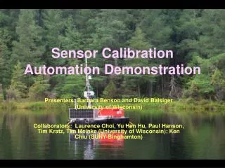
First reflectance CDS outside for December 2011 reflectance measurements Ratio of scene data (buildings, trees, cloudy sky, and clear sky ) to reference gives relative reflectance Photo shows SOLARIS instrument with integrated optics and detector package mounted to a motorized telescope mount with the detector readout electronics
First reflectance Image at right is single band System scanned in vertical direction to create the 2-D spatial image CDS is pushbroom design One dimension gives spatial information 2nd dimension gives spectral Spatial distortion caused by oversampling in the scan direction
First reflectance Three-band mix of geometrically corrected data along with COTS digital photo of scene
First reflectance Red edge is in the 700-750 range
Laboratory-based spectral calibration Diffusely reflected lamp Direct view of mercury lamp
Laboratory-based radiometric calibration Sphere-based source that fills field and aperture Mean of 20 frames of associated dark measurements Mean of 20 frames of sphere measurements Spatial variability of output is result of operating detectors at ambient Results in larger dark current as well Sphere – dark
Laboratory-based radiometric calibration SOLARIS detector package allows for large dynamic range but requires linearization Based on TIRS detector package built at GSFC Copy TIRS approach for SOLARIS data SOLARIS at 4 channels TIRS example
Lunar collection Image of the moon collected on March 1 Evaluate spatial quality of imagery Develop techniques for pointing and re-sampling Blurred edge of moon is result of detector bleed over from operating with lower voltage bias
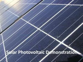
Solar collection SOLARIS operated with two neutral density filters giving 10-5 transmittance Data will be used to evaluate for optical scattering effects Tests of perforated plate attenuator coming soon
SOLARIS + SIRCUS first light SIRCUS used for preliminary spectral characterization on April 7 20-m fiber from SIRCUS
SIRCUS results Single wavelength image Results for multiple SOLARIS bands Multiple single wavelength images for single SOLARIS band
CDS Integration, Test, & Cal. Flow Current status FY 2012 FY 2013 FY 2014
Summary Goal for FY 2012 is to demonstrate a 2-3% calibrated instrument with error budget Blue box CDS completed in October 2011 with prototype grating and uncooled detectors Verification of laboratory and scene accuracies awaits improvements to detector cooling package expected by May Final version of grating recently delivered Solar and lunar measurements have been made Initial SIRCUS-based spectral response just completed Will deliver a quantitative error budget Red box CDS will be completed by end September
Summary Plans for FY 2013 and beyond concentrate on taking SOLARIS to the 1% plateau Timing depends on actual funding allocations Personnel numbers may limit some development Susceptible to hardware failures Improvement to laboratory calibration are funding dependent Successful CDS effort will Develop and test sensor model development Demonstrate error budget for reflectance retrieval Produce a peer-reviewed SI traceability for CLARREO-like measurements Evaluation of absolute solar irradiance calibration Lunar model verification from ground-based collects
Summary Collaborative efforts with NIST will continue to be critical “Operational” use of SIRCUS Extension to wavelengths >1 micrometer Broadband calibration approaches (HIP) Calibration approaches will be demonstrated Laboratory calibration protocols Error budget demonstration Reflectance retrieval Stray light characterization Instrument model assessment SOLARIS CDS will play a key role demonstrating CLARREO-quality error budgets