Download
1 / 51
510 likes | 705 Vues
Anti-parallel and Component Reconnection at the Magnetopause (Southward IMF). K.J. Trattner, J.S. Mulcock, S.M. Petrinec and S.A. Fuselier Lockheed Martin ATC, Palo Alto, CA. Outline. Reconnection Location Overview Methods: Ion Jets, Imaging, 3D Cutoffs 3D Low Velocity Cutoffs

E N D
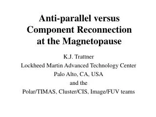
Anti-parallel and Component Reconnection at the Magnetopause(Southward IMF) K.J. Trattner, J.S. Mulcock, S.M. Petrinec and S.A. Fuselier Lockheed Martin ATC, Palo Alto, CA
Outline • Reconnection Location Overview • Methods: Ion Jets, Imaging, 3D Cutoffs • 3D Low Velocity Cutoffs • Data: 3D Plasma Distributions in the Cusp • Mapping Distance along the Geomagnetic Field • Examples • Anti-parallel Reconnection • Tilted X-line • Seasonal Effects, IMF Bx Effects • Summary
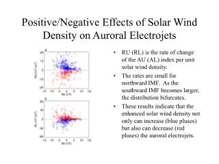
Reconnection with Southward IMF CONVECTION Lockwood [1995]
Large Scale Reconnection GeometrySouthward IMF: Two ModelsAnti-Parallel vs. Tilted X Line Reconnection Gosling et al. (1991) Fuselier et al. (2002)
Anti-Parallel Reconnection Anti-parallel Reconnection sites for large IMF By conditions Crooker [1979]
Anti-Parallel Reconnection Pattern of the anti-parallel reconnection sites for various IMF conditions Luhmann et al. [1984]
Component Reconnection Tilted X-Line Tilted X-Line through the Subsolar Point Gonzalez and Mozer [1974]
Component Reconnection Tilted X-Line Equal Parallel Components Sonnerup [1974] Unequal Perpendicular Components Cowley [1976]
Component Reconnection Tilted X-Line Equal Perpendicular Components, No Dipole Tilt, Perfect IMF draping Moore et al. [2002]
Methods • Ion Beams in the Boundary Layers • IMAGE/FUV Observations
Ion Jets emanating from X-Line observed at the Magnetopause Ion Jet Studies: Gosling et al. [1990, 1991] Scurry et al. [1994] Phan et al. [1996] Fuselier et al. [2005] Phan et al. [2006] ………. Phan et al. [2000]
IMAGE: Precipitation is Different for the Two Types of Reconnection Anti-Parallel Tilted Line The Key Difference is The Flux Near Noon
IMAGE Distinguishes Anti-Parallel and Component Reconnection View from Sun View from Sun Tilted Neutral Line Anti-Parallel 30 December 2001 2208:06 UT IMAGE SI12 Proton Aurora Neutral Line Mapped to the Ionosphere Continuous Across Noon Noontime Gap Noontime Gap – Anti-Parallel Reconnection
Is This the End of Component Reconnection? – Another Event View from Sun View from Sun Tilted Neutral Line Anti-Parallel 11 January 2002 0658:00 UT IMAGE SI12 Proton Aurora Neutral Line Mapped to the Ionosphere Noontime Gap Continuous Across Noon No Noontime Gap – Component Reconnection
Does Reconnection “Turn Off” When the IMF Rotates? Reconnection is continuous, even when the IMF is changing IMF change >>>> Simple change in the location
Methods 3. 3D Low Velocity Cutoff Method
Plasma Entry Precipitating ions in the cusp [Reiff et al., 1977; Escoubet et al., 1997] Magnetopause Fast Particle Slow Particle Magnetospheric Cusp Solar Wind Precipitating cusp ions experience a velocity filter effect with lower energies convecting further poleward [Rosenbauer et al., 1975; Shelley et al., 1976]
Cusp Ion Energy Dispersion for Southward IMF Velocity Filter Effect: Decreasing Ion Energy with Increasing Latitude
Ion Dispersion in the Cusp: Distance to the Reconnection SiteOnsager et al. [1990], Fuselier et al. [2000], Trattner et al. [2004] Assumes: “Instantaneous” acceleration Simple Field Line Structure
Mapping ModificationAvoid Open Magnetic Field Lines A Satellite in the Cusp is always on Open Field Lines Mapping to the Magnetospheric Tail Reconnection during IMF south conditions occurs on closed field lines on the dayside
Field Line Draping T96 Model Cooling Draping Model [2001]
Polar/TIMAS Cusp CrossingNorthern Hemisphere Cusp Open Field Line Region | Closed | Field | Lines 2-Year Study : 130 Cusp crossings B(z) < 0 all clock angles
Polar/TIMAS 3D Plasma Measurements • 2 Year Study: • 130 cusp crossings • 3000 H+ distributions • BZ<0 all clock angles • - limited the small BX • Distance to Reconnection Site: • -Tsyganenko Model • MP shear at Reconnection Site • -Cooling et al. (2001) • draping model Precipitating Ions Mirrored Ions Mirrored Precipitating Vm Ve
Polar/TIMAS 3D Plasma Measurements Precipitating Ions Mirrored Ions Mirrored Precipitating Mirrored Precipitating Vm Ve
Tracing the Reconnection Region from both Hemispheres Clock Angle: 252° Cluster Cusp Crossing Northern Polar Region Polar Cusp Crossing Southern Polar Region Trattner et al. (2006) MP Shear Angle Plots: Tsyg96 – Cooling et al. (2001)
Anti-Parallel Reconnection (MLT: 15:10) March 4, 1998: Clock Angle 191° • MP Shear Angles: • RED – antiparallel • BLACK – parallel • WHITE in RED – • within 3° of anti-|| Black Circle: Terminator MP Share Angle Calculation based on T96 and Cooling et al. (2001)
Anti-Parallel Reconnection (MLT: 10:25) November 6, 1997: Clock Angle 195°
Polar/TIMAS Cusp Crossings In which Hemisphere is reconnection Located? Southern Hemisphere Northern Hemisphere
Anti-Parallel ReconnectionApril 11, 1996 CA: 175° March 29, 1998 CA: 174°
Tilted X Line (MLT: 13:30)September 20, 1997: Clock Angle 130°
Tilted X Line (MLT: 13:30)September 20, 1997: Clock Angle 130°
Seasonal Effects (Summer)
Tilted X-Line Summer Events The Line of Maximum Magnetic Shear is shifted to the Southern Hemisphere.
Seasonal Effects (Equinox)
Tilted X-Line Equinox Events The Line of Maximum Magnetic Shear crosses the Sub-Solar Point.
Seasonal Effects (Winter)
Tilted X-Line Winter Events The Line of Maximum Magnetic Shear is shifted to the Northern Hemisphere.
Large IMF Bx Events The Reconnection Line is Bifurcated and in the Anti-Parallel Reconnection Region.
Summary and Conclusion • Polar Cusp Crossings in the Northern Hemisphere. • Continuous Reconnection (Polar, Cluster, Image) • Long Reconnection Lines • Anti-Parallel Reconnection Location for Clock Angles of ± 20° – 30° from Southward IMF • Tilted X-Line Reconnection Location for Larger Deviations from Southward IMF • Seasonal Effects for Tilted X-Line • BX effect: Large BX – anti-parallel reconnection
Component Reconnection Tilted X-Line Tilted X-Line through the Subsolar Point? Cowley and Owen [1989]