SPI
SPI. Serial Peripheral Interface. SPI. Serial Peripheral Interface is communication between two devices, one bit at a time s equential one bit at time over a computer bus ( a subsystem that transfers data Between components inside of a computer) or a communication channel (wire

SPI
E N D
Presentation Transcript
SPI Serial Peripheral Interface
SPI Serial Peripheral Interface is communication between two devices, one bit at a time sequential one bit at time over a computer bus ( a subsystem that transfers data Between components inside of a computer) or a communication channel (wire or wave transmission). Serial Peripheral Interface (SPI) is a synchronous serial data protocol used by microcontrollers for communicating with one or more peripheral devices quickly over short distances. It can also be used for communication between two microcontrollers.
SPI Serial Peripheral Interface is a synchronous data link that operates in full duplex mode which means that communication can occur in both directions simultaneously. cell phones and two way radios are full duplex devices. Devices operate in a master/ slave mode where the master initiates and directs the communication of data. Some times SPI is called a 4-wire serial bus.
SPI SPI has 4 logic signals. A logic signal is the finite number of states a signal can have. The logic signal we are most familiar with is binary 0s and 1s. Logic levels are represented by a difference in voltage. SCLK MOSI MISO SS
SCLK Serial Clock is output from the master. The serial clock sets the frequency of communication To begin a communication, the bus master first configures the clock, using a frequency less than or equal to the maximum frequency the slave device supports. Such frequencies are commonly in the range of 1–100 MHz The clock pulses which synchronize data transmission generated by the master
SS Slave Select is active when the logic signal is low. If there is only one slave device then the SS pin maybe fixed at logic low. If there are multiple slave devices then the signal is low signifying which of the devices is “conversing” with the master. tThe pin on each device that the master can use to enable and disable specific devices. The master then transmits the appropriate chip select bit for the desired chip to a logic 0. A logic 0 is transmitted because the chip select line is active low, meaning its off state is a logic 1; on is asserted with a logic 0.
MOSI Master Output, Slave Input. Output from the Master. Serial data in. The Master line for sending data to the peripherals, During each SPI clock cycle, a full duplex data transmission occurs: the master sends a bit on the MOSI line; the slave reads it from that same line
MISO Master Input, Slave Output. Input from the Master. Serial data out. The Slave line for sending data to the master. The slave sends a bit on the MISO line; the master reads it from that same line. Transmissions may involve any number of clock cycles. When there is no more data to be transmitted, the master stops toggling its clock. Normally, it then deselects the slave.
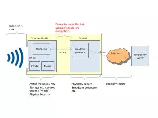
Multiple Slave Configuration When a device's Slave Select pin is low, it communicates with the master. When it's high, it ignores the master. This allows you to have multiple SPI devices sharing the same MISO, MOSI, and CLK lines.
What components or devices have we used that use SPI? There are three so far.
Sensors: temperature, pressure, ADC, touchscreens, video game controllers Control devices: audio codecs, digital potentiometers, DAC Camera lenses: Canon EF lens mount Communications: Ethernet, USB, USART, CAN, IEEE 802.15.4, IEEE 802.11, handheld video games Memory: flash and EEPROM Real-time clocks LCD displays
Sensors: temperature, pressure, ADC, touchscreens, video game controllers Control devices: audio codecs, digital potentiometers, DAC Camera lenses: Canon EF lens mount Communications: Ethernet, USB, USART, CAN, IEEE 802.15.4, IEEE 802.11, handheld video games Memory: flash and EEPROM Real-time clocks LCD displays
LM335 Temperature Sensor The LM335A works like a Zenerdiode with a breakdown voltage proportional to absolute temperature at 10mV/°K. Hook up a resistor from 5V and GND, and the LM335A will output an analog voltage of 2.98V (298 Kelvin is 25C or room temperature). The sensor can operate continuously from −40°C to 100°C. Calibration of the sensor requires a pot connected across the sensor, with the wiper of the potentiometer connected to the adjustment pin of the LM335. A Zenner diode allows current to flow in the forward direction in the same manner as an ideal diode, but will also permit it to flow in the reverse direction when the voltage is above a certain value
D18BS20 Temperature Sensor Very similar to the LM335, but each has its own unique 64 bit number etched onto it so that The sensor can be identified. Why might that be useful?