Systems Analysis
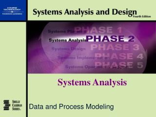
Data and Process Modeling. Systems Analysis. Chapter 4. Data and Process Modeling. Objectives. Describe data and process modeling concepts and tools Explain how structured analysis describes an information system

Systems Analysis
E N D
Presentation Transcript
Data and Process Modeling Systems Analysis
Chapter 4 Data and Process Modeling Systems Analysis and Design Fourth Edition
Objectives • Describe data and process modeling concepts and tools • Explain how structured analysis describes an information system • Describe the symbols used in data flow diagrams and explain the rules for their use • Explain the sequence of data flow diagrams, from general to specific Systems Analysis and Design Fourth Edition
Objectives • Explain how to level and balance a set of data flow diagrams • Draw a complete set of data flow diagrams for an information system • Describe how a data dictionary is used and what it contains Systems Analysis and Design Fourth Edition
Objectives • Explain the interaction among process flow charts, data flow diagrams, and the data dictionary • Describe the relationship between logical and physical models Systems Analysis and Design Fourth Edition
Systems analysis phase has three stages Requirements determination (Chapter 3) Requirements analysis (Chapters 4 & 5) Evaluation of alternatives (Chapter 6) Introduction Systems Analysis and Design Fourth Edition
Data Flow Diagrams • Data flow diagrams (DFDs) show how data moves through an information system • DFDs represent a logical model that shows what a system does, not how it does it Systems Analysis and Design Fourth Edition
Data Flow Diagrams • Data flow diagram symbols • Four basic symbols • Process • Data flow • Data store • External entity • Two popular symbol sets • Gane and Sarson • Yourdon Systems Analysis and Design Fourth Edition
Data Flow Diagrams • Process symbol • Symbol is a rectangle with rounded corners • Receive input data and produces output • Output has a different form, or content, or both • Details are shown in a process flowchart • In DFDs the process symbol appears as a black box, underlying details not shown • The process name identifies a specific function and consists of a verb and an adjective, if necessary, followed by a single noun Systems Analysis and Design Fourth Edition
Data Flow Diagrams • Data flow symbol • Symbol is a line with an arrowhead showing direction • A path for data to move from one part of the system to another • Represents one or more data items • At least one data flow must enter and exit each process • A data flow name consists of a singular noun and an adjective, if needed Systems Analysis and Design Fourth Edition
Data Flow Diagrams • Data store symbol • Symbol is a rectangle open on the right side • Data store also is called a data repository • Represents data that is retained for later processing • Must be connected to a process with a data flow • Must have at least one outgoing and incoming data flow • A data store name is a plural name consisting of a noun and adjectives, if needed Systems Analysis and Design Fourth Edition
Data Flow Diagrams • External entity symbol • Symbol is a square, usually shaded • Represents a person, organization, or other system that provides data or receives output from the system • External entities are called terminators • Source (supplies data to the system) • Sink (receives data from the system) • An external entity name is a singular noun • Must follow specific rules for connecting DFD symbols Systems Analysis and Design Fourth Edition
Data Flow Diagrams Systems Analysis and Design Fourth Edition
Data Flow Diagrams • Context diagrams • Top-level view that shows the systems’ boundaries scope • Represent the results of fact-finding • One process symbol, numbered 0 (zero) is drawn in the center • Data flows connect the process to the entities • Abbreviated symbols can be used to identify entities Systems Analysis and Design Fourth Edition
Data Flow Diagrams • Conventions for data flow diagrams • Each context diagram must fit on one page • Process name in the context diagram should be the name of the information system • Use unique names within each set of symbols • Do not cross lines • Use abbreviated identifications • Use a unique reference number for each process symbol Systems Analysis and Design Fourth Edition
Data Flow Diagrams • Diagram 0 • Displays more detail than the context diagram • Shows entities, major processes, data flows, and data stores Systems Analysis and Design Fourth Edition
Data Flow Diagrams • Diagram 0 • Displays more detail than the context diagram • Shows entities, major processes, data flows, and data stores • Can contain diverging data flows • Exploded (partitioned or decomposed) version of process 0 • Diagram 0 is the child of the parentcontext diagram • Also can be called an overview or level 0 diagram • Can contain functional primitives Systems Analysis and Design Fourth Edition
Data Flow Diagrams • Lower-level diagrams • Usually necessary to show more detail • Design must consider: • Leveling: Process of drawing increasingly detailed diagrams. Also called exploding, partitioning, or decomposing • Balancing: Maintains consistency among an entire set of DFDs. Parent’s input and output data flows are preserved on the child • Data DFDs stores: Might not appear on higher-level. Are shown on the the highest-level DFD that has two or more processes using that data store Systems Analysis and Design Fourth Edition
Data Flow Diagrams • Strategies for developing DFDs • Main objective is to ensure that your model is accurate and easy to understand • A diagram should have no more than nine process symbols Systems Analysis and Design Fourth Edition
Data Dictionary • Also called data repository • Documents specific facts about the system • Data flows • Data stores • External entities • Processes • Data elements (data items, fields) • Records (data structures) Systems Analysis and Design Fourth Edition
Data Dictionary • Documenting the data stores • Must document every data store • All major characteristics must be recorded and described • Data dictionary serves as a central storehouse for documentation • Using this data, you can produce many valuable reports Systems Analysis and Design Fourth Edition
Logical Versus Physical Models • Sequence of models • A physical model shows how the systems’ requirements are implemented • Create a physical model of the current system • Develop a logical model of the current system • After the current system is understood, create a logical model of the new system Systems Analysis and Design Fourth Edition
Logical Versus Physical Models • Four-model approach • Four models • Physical model of the current system • Logical model of the current system • Logical model of the new system • Physical model of the new system Systems Analysis and Design Fourth Edition
Logical Versus Physical Models • Four-model approach • Major benefit is having a better grasp of the current system functions before making any modifications • Major disadvantage is added time and cost needed to develop a logical and physical model of the current system Systems Analysis and Design Fourth Edition