Download
1 / 29
350 likes | 702 Vues
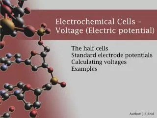
ELECTROCHEMICAL SYSTEMS FOR ELECTRIC POWER GENERATION. Dzmitry Malevich Depatrment of Chemistry and Biochemistry University of Guelph. Electrolysis / Power consumption. Chemical Reactions. Electric Power. Electrochemical battery / Power generation.

E N D
ELECTROCHEMICAL SYSTEMS FOR ELECTRIC POWER GENERATION Dzmitry Malevich Depatrment of Chemistry and Biochemistry University of Guelph
Electrolysis / Power consumption Chemical Reactions Electric Power Electrochemical battery / Power generation Electric power conversion in electrochemistry
Volta’s battery (1800) Alessandro Volta 1745 - 1827 Paper moisturized with NaCl solution Cu Zn
Me20 - ne- = Me2n+ Me2n+ - ne- = Me20 ANODE CATHODE Me2 Me1 Me1n+ SO42- Salt Bridge Principles of power generation in the electrochemicalsystems Me2n+ SO42-
IMPORTANT NOTICE ! Electrolysis System consumes energy G>0 ANODE + CATHODE - Battery System releases energy G<0 ANODE - CATHODE + (oxidation process) (oxidation process) (reduction process) (reduction process)
Me20 - ne- = Me2n+ Me2n+ - ne- = Me20 ANODE CATHODE Me2 Me1 or Membrane Me1n+ SO42- Principles of power generation in the electrochemicalsystems Diaphragm Me2n+ SO42-
Modern Zinc-Manganese battery Anode: Zn Zn2+ + 2e- Cathode: 2MnO2 + 2H2O +2e- 2MnOOH + 2OH- Electrolyte: Zn2+ 2NH4Cl +2OH- Zn(NH3)Cl2 + 2H2O 2MnO2 + Zn + 2NH4Cl 2MnOOH + Zn(NH3)Cl2 Gas space Zn-container MnO2 paste (cathode) Carbon rod Gel electrolyte Primary batteries Leclanché’s battery (1866) Georges Leclanché (1839-1882) Seal Zn-container MnO2 paste (cathode) Carbon rod NH4OH electrolyte
Zinc-Manganese alkaline battery MnO2 paste (cathode) Porous Zn (anode) Gel electrolyte Zinc-Air battery Anode: Zn + 2OH- - 2e- Zn(OH)2 Cathode: 1/2 O2 + H2O + 2e- Zn(OH)2 Primary batteries Anode: Zn + 2OH- - 2e- Zn(OH)2 Cathode: MnO2 + H2O +1e- MnOOH + OH-aaaaaaaaa MnOOH + H2O +e- Mn(OH)2 + OH-
E=2.06 V Lead-acid battery Pb PbO2 Safety valve 36% H2SO4 discharge discharge PbO2+(2H++SO42-)+2H++2e- Pb+(2H++SO42-)-2e- charge charge PbSO4+H2O PbSO4+ 2H+ Lead dioxide paste in Pb-mesh (cathode) PbSO4 PbSO4 Lead paste in Pb-mesh (anode) Porous separator discharge PbO2 + Pb + H2SO4 2PbSO4 + 2H2O Secondary (rechargeable) batteries Lead-acid battery
Discharge Cathode: LiMeO2 - xe- Li1-xMeO2 + xLi+ Anode: C + xLi+ + xe- CLix CHARGE CHARGE DISCHARGE DISCHARGE Charge Negative terminal Separator Aluminum can Positive terminal Secondary (rechargeable) batteries Lithium-ion battery Anode (CLix) Cathode (LiMexOy) LiCoO2 -utilized for commercial batteries LiNiO2, LiMn2O4-prospective
CHARGE CHARGE DISCHARGE DISCHARGE Picture from: T. Takamura / Solid State Ionics 152-153(2002)19 Secondary (rechargeable) batteries Nickel-Metal Hydride battery Cathode: NiOOH + H2O - e- Ni(OH)2 + OH- Anode: Me + OH- + e- Me + H2O
Reductant (fuel) Oxidant Primary batteries Secondary batteries Fuel cells Reaction products (exhaust) POWER POWER Recharge POWER POWER Types of the electrochemical system for electric power generation
O2 H2 4H+ + 4e- 2H2 2H2O - 4e- O2 + 4H+ Grove’s fuel cell (1839) Sir William Grove 1811–1896
Raising the current: • Increasing the temperature • Increasing the area of eelectrode electrolyte interface • The use of catalyst Connection of cells in series Cell stack ANODE ANODE ANODE ANODE ANODE ANODE ANODE ANODE ELECTROLYTE ELECTROLYTE ELECTROLYTE ELECTROLYTE ELECTROLYTE ELECTROLYTE ELECTROLYTE ELECTROLYTE CATHODE CATHODE CATHODE CATHODE CATHODE CATHODE CATHODE CATHODE Bipolar electrode Anode catalyst Cathode catalyst H2 O2 Stack of several hundred Electrolyte frame Bipolar plate Fuel Cells performance improving Raising the voltage:
Phosphoric Acid Fuel Cell (PAFC) Electrolyte in SiC porous matrix O2 Pt-particles catalysts (anode or cathode) Gas (H2 or O2) PACF parameters: current density - 200- 400 mA cm-2 single cell voltage - 600-800 mV temperature - 220 oC At atmospheric pressure H2
Reaction zone e- e- Gas Diffusion Electrode Dry zone (no reaction) H2 Electrode Gas Electrolyte Reaction zone Dip zone (reaction is slow because diffusion limitation)
H2 Disadvantages of liquid electrolyte fuel cell Low operation temperature ! (reaction is slow, expensive catalysts are needed to produce valuable current) Difficulties in three-phase interface maintaining ! Strong fuel crossover! Recombination (no electron transfer through outer socket - energy loss) O2 Anode Liquid electrolyte Cathode
Proton Exchange Membrane Fuel Cell (PEMFC) H2O +Air (O2) H2 H+ Nafion® membrane Catalyst support (carbon cloth) Current collector / gas distributor H2 crossover H2 Air (O2) + -
Polyethylene F H F F H F F H F H F F F H F F F H H H Polymerization C C C C C C C C C C C C C C C C C C C C H H F H F H O F F F H F H F F H F H F F Fluorination Grafting O F F F F C C C C F F F F Polytetrafluoroethylene (PTFE, Teflon®) O S O - Nafion® (DuPont) O H+ Proton Exchange Membrane (PEM) Ethylene
CH4 + O2 CO2 + H2O Catalyst HEAT Stainless still Catalyst CH4 + H2O H2 + COx Fuel reforming CnHm + nH2O = nCO + (m/2 + n)H2 CH4 + H2O = CO + 3H2 CO + H2O = CO2 + H2 CH3OH + H2O = 3 H2 + CO2 T~ 500 oC, Ni-catalyst T~ 250 oC, Ni-catalyst no CO
Direct Methanol Fuel Cell (DMFC) CH3OH + H2O + CO2 H2O +Air (O2) H+ Nafion® membrane Catalyst support (carbon cloth) Current collector / fuel distributor CH3OH crossover CH3OH + H2O Air (O2) + -
+ + + + + + ê ê ê ê ê ê Methanol oxidation mechanism carbon oxygen hydrogen Pt Pt
Direct Methanol Fuel Cell (DMFC) Theoretical voltage = 1.182 V Real voltage Current 0.046 1.23 Potential vs. HRE, V CH3OH + H2O = CO2 + 6H+ + 6e- 3/2O2 + 6H+ + 6e- = 3H2O
Ru Carbon monoxide tolerant anode carbon oxygen hydrogen Pt
Methanol crossover through Nafion From M.P. Hogharth and G.A. Hards, Platinum Metals Rev. 40 (1996) 150 Temperature oC Current density, A cm-2 Crossover rate, A cm-2 90 0.1 0 .32 90 0.2 0.30 90 0.3 0.27 S. R. Narayanan, DOE/ONR Fuel Cell Workshop, Baltimore, MD, Oct 6-8 1999 Number of methanol moles (Nm) transported by crossover can be calculated by Faraday low: Nm = jc·S·t/n·F, where j - current density(crossover rate) , S - membrane area, t - time, n-number of electrons (n=6 for methanol oxidation), F - Faraday constant
Catalysts for fuel cells with polymer electrolyte PEMFC DMFC Anode: Pt or PtRu (~50% Pt) black 1-10 nm Cathode: Pt (~50% Pt) black 1-10 nm Anode: usually PtRu (~50% Pt) black 1-10 nm Cathode: Pt (~50% Pt) black 1-10 nm Catalysts are supported on carbon nanoparticles (50-200 nm, for example Vulcan XC72) Catalysts are usually unsupported Precious metals load is 0.2 - 0.5 mg cm-2 for both electrodes Precious metals load is 1.0 - 10.0 mg cm-2 for both electrodes Power density - 100 mW cm -2 at cell voltage 0.5 V (t=90 oC, CH3OH concentration - 0.75 M) Power density - 500 mW cm -2 at cell voltage 0.5 V (t=80 oC, CO-free hydrogen) Catalysts cost ~ 0.8 g per kW ( ~140 CAN$ per kW) Catalysts cost ~ 10 g per kW ( ~1750 CAN$ per kW)
Molten Carbonate Fuel Cell (MCFC) Anode Porous electrolyte support Cathode LiNiO2 or LiCoO2 NiCr alloy Alkali metal carbonates in LiAlO2 matrix H2 +CO2 +H2O O2 +CO2 CO32- H2 O2 +CO2 0.2 - 1.5 mm 0.5 - 1.0 mm 0.5 - 1.0 mm T= 600-700 oC O2 + 2CO2 + 4e - = 2CO32- 2H2 + 2CO32- - 4e- = 2H2O + 2CO2
Air Air Solid Oxide Fuel Cell (SOFC) Anode Electrolyte Cathode Sr doped La-manganite H2 +H2O O2 O2- H2 O2 YSZ 2H2 + 2O2- - 4e - = 2H2O O2 + 4e - = O2- Ni+YSZ T= 800-1100 oC Electrolyte Anode Fuel Cathode
Types of Fuel Cells Operating temperature Power range Mobile ion Phosphoric Acid Fuel Cell (PAFC) H+ ~220 oC 10 - 1000 kW H + 50 - 100 oC 1 - 100 kW H + 50 - 100 oC 1 - 100 kW CO32- ~650 oC 0.1 - 10 MW O2- 500 - 1000 oC 0.01 - 10 MW Proton Exchange Membrane Fuel Cell (PEMFC) Direct Methanol Fuel Cell (DMFC) Molten Carbonate Fuel Cell (MCFC) Solid Oxide Fuel Cell (SOFC)