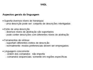
Le VHDL
480 likes | 673 Vues
Le VHDL. De nos jours, les circuits numériques de haute performance sont habituellement créés à partir de descriptions en langages de haut niveau. Nous allons maintenant parler de l’un de ces langages, le VHDL. Le VHDL: Qu’est-ce que c’est, et à quoi cela sert-il?.

Le VHDL
E N D
Presentation Transcript
Le VHDL De nos jours, les circuits numériques de haute performance sont habituellement créés à partir de descriptions en langages de haut niveau. Nous allons maintenant parler de l’un de ces langages, le VHDL
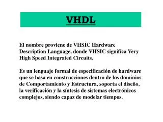
Le VHDL: Qu’est-ce que c’est, et à quoi cela sert-il? • VHDL: VHSIC Hardware Description Language • VHSIC: Very High Speed Integrated Circuit (projet de grande envergure du DoD (Departement of Defense) Américain, mis en place dans les années ’80 • Principe de base: Définir un langage de description de matériel qui puisse être utilisé pour simuler du matériel numérique • Extension: Utilisation du même langage pour la synthèse automatique de circuits
VHDL: Est-ce le seul HDL? • Il existe plusieurs autres langages de description de matériel, entre autres: • Verilog (Très populaire aux États-Unis, utilisé aussi en Europe, au Japon et au Canada) • UDL/1 (Utilisé à un certain moment au Japon) • Estérel (langage académique – Français) • HardwareC (langage académique – Stanford) • Verilog est plus simple que le VHDL, mais est un peu moins utilisé
« Design Flow » moderne Simulation comportermentale Design fonctionnel Simulation RTL Validation Design « Register Transfer Level » Simulation logique Vérification Simulation de fautes Design Logique Analyse des délais Analyse du circuit « Design Rule Checking » Design « Physique »
Concepts de base • Description du système: • Structurale • Comportementale (behavioral) • Événements • Délais de propagation • Concurrence • Timing: • Synchrone • Asynchrone • Signaux: • Forme • Valeur • Partage • Simulation d’événements discrets
Pourquoi utiliser des langages HDL? • Pour accélérer la conception de circuits (raison économique) • Pour permettre la conception de circuits très complexes (150 millions de portes logiques d’ici 5 ans) • Pour pouvoir représenter les systèmes numériques selon les différents axes d’abstraction
Pertes de revenus Délai Pourquoi mettre en marché plus rapidement? Revenus maximum Augmentation du marché Revenus Déclin du marché Temps
Le « Y » de Gadjsky Structural Comportemental Algorithmes Processeurs Register transfer Registres Expressions Booléennes Portes Fonctions de transfert Transistors Cellules Modules Circuits Printed Circuit Board Physique
Valeur des signaux • À la base, tout système numérique est constitué de signaux binaires. VHDL supporte le ‘bit’ au plus bas niveau. • Valeur possible du bit: 0 ou 1 • Est-ce suffisant?
X H L W Z U - 1 0 Valeur Inconnu - Forcé 1 - Forcé 0 - Faible Interprétation Inconnu - Faible Uninitialized (non-initialisé) 0 - Forcé Don’t Care 1 - Faible Haute impédance Valeur des signaux Standard IEEE 1164:
Premier concept de base: les entités (entity) • Première étape de définition de matériel: définir l’interface • Comment: à l’aide de la déclaration « entity »
a sum b carry Les « entity » • L’interface externe du circuit ci-haut est spécifiée par la déclaration « entity » suivante: entity half_adder is port(a, b: in bit; sum, carry: out bit); end half_adder;
Exemple d’entity: multiplexeur de bus entity mux is port (I0, I1 : in std_ulogic_vector (7 downto 0); I2, I3: in std_ulogic_vector (7 downto 0); Sel: in std_ulogic_vector (1 downto 0); z : out std_ulogic_vector (7 downto 0)); end mux;
Exemple d’entity: Flip-flop entity D_ff is port (D,Clk, S, R: in std_ulogic; Q, Qbar: out std_ulogic); end D_ff;
Deuxième concept de base: les énoncés concurrents • Il faut être capable de définir la fonctionnalité de notre système, qui représente ce que le matériel devra effectuer • Puisqu’on parle de matériel, tout ce qui est décrit va « s’exécuter » en parallèle • Pour décrire la fonctionnalité d’un système, on utilise la déclaration « architecture », qui implicitement contient des énoncés concurrents
Exemple d’architecture: un demi-additionneur library IEEE; use IEEE.std_logic_1164.all; entity half_adder is port(a, b: in bit; sum, carry: out bit); end half_adder; architecture comportement_concurrent of half_adder is begin sum <= (a xor b) after 5 ns; carry <= (a and b) after 5 ns; end comportement_concurrent;
Signaux à source multiples • Qu’arrive-t-il si un signal est produit par plus d’une source (e.g. élément d’un bus)? • Qu’arrive-t-il si les différentes sources ne déterminent pas la même valeur? • On utilise une fonction de « résolution » pour traiter ces cas • Dans la librairie IEEE, le type « std_logic » du standard 1164 est résolu
Assignations conditionnelles • On peut utiliser une assignation conditionnelle pour définir la valeur d’un signal: library IEEE; use IEEE.std_logic_1164.all; entity mux4 is port (In0, In1, In2, In3: in std_logic_vector (7 downto 0); S0, S1: in std_logic; z: out std_logic_vector (7 downto 0)); end mux4; architecture comportemental of mux4 is begin z <= In0 after 5 ns when S0 = ‘0’ and S1 = ‘0’ else In1 after 5 ns when S0 = ‘0’ and S1 = ‘1’ else In2 after 5 ns when S0 = ‘1’ and S1 = ‘0’ else In3 after 5 ns when S0 = ‘1’ and S1 = ‘1’ else ‘00000000’ after 5 ns; end comportemental;
Utilisation de sélecteurs • Lorsqu’il y a un grand nombre de possibilités qui sont toutes énumérées, on peut utiliser un sélecteur
Utilisation de sélecteurs – exemple library IEEE; use IEEE.std_logic_1164.all; entity memoire is port (addr1,addr2: in std_logic_vector (2 downto 0); mem1: out std_logic_vector (31 downto 0)); end memoire; architecture comportemental of memoire is signal reg0, reg1, reg2, reg3: std_logic_vector (31 downto 0):= to_stdlogicvector(x’’1234AB’’); signal reg4, reg5, reg6, reg7: std_logic_vector (31 downto 0):= to_stdlogicvector(x’’5678FF’’); begin with addr1 select mem1 <= reg0 after 5 ns when ‘‘000’’; reg1 after 5 ns when ‘‘001’’; reg2 after 5 ns when ‘‘010’’; reg3 after 5 ns when ‘‘011’’; reg4 after 5 ns when others; end comportemental;
Les délais • VHDL permet de modéliser différents types de délais, qui sont utiles lors des simulations: • Délais d’inertie (inertial delay): représentent la durée minimum d’une entrée pour que son effet puisse être observé à la sortie. Utile pour tenir compte du temps de montée/descente • E.g.: sum <= reject 2 ns inertial (a xor b) after 5 ns; • Délais de transport: représentent le délai encouru par les interconnections. Utile pour tenir compte des délais RC dans les longs fils • E.g.: sum <= transport (a xor b) after 5 ns; • Délais « delta »: utilisés à l’interne par les simulateurs pour ordonner l’arrivée des signaux
s1 a sum b s2 carry a inertie b sum transport carry s1 s2 2 4 6 8 10 12 Temps (ns) Les délais: exemple library IEEE; use IEEE.std_logic_1164.all; entity half_adder is port(a, b: in std_logic; sum, carry: out std_logic); end half_adder; architecture delai_transport of half_adder is signal s1, s2: std_logic := ‘0’; begin s1 <= (a xor b) after 2 ns; s2 <= (a and b) after 2 ns; sum <= transport s1 after 4 ns; carry <= transport s2 after 4 ns; end delai_transport;
s1 s3 a z b s4 s2 Les délais: exemple library IEEE; use IEEE.std_logic_1164.all; entity circuit is port(a, b: in std_logic; z: out std_logic); end circuit; architecture circ of circuit is signal s1, s2, s3, s4: std_logic; begin s1 <= not a; s2 <= not b; s3 <= not ( s1 and b); s4 <= not (s2 and a); z <= not (s3 and s4); end circ; a b s1 s2 s3 s4 z 2 4 6 8 10 12 Temps (ns)
s1 s3 a z b s4 s2 a b s1 s2 s3 s4 z 2 4 6 8 10 12 Temps (ns) Les délais: exemple b s2 s3 z 2 2 3 4 Temps (ns)
Modélisation de comportement • Pour décrire des systèmes plus complexes qu’un petit groupe de simples portes logiques, nous devons ajouter un nouveau concept: le processus (process) • Le «process » a une liste de dépendance (dependency list). Lorsqu’un ou plusieurs signaux de la liste sont modifiés, le process est enclenché
Les processus: exemple begin addr_int := to_integer(addr (1 downto 0)); if (Mem_wr = ‘1’ then data_memo(addr_int) := wr_data; elsif Mem_rd = ‘1’ then rd_data <= data_memo(addr_int); end if; end process memo_proc; end comport; library IEEE; use IEEE.std_logic_1164.all; use IEEE.std_logic_arith.all; entity mem is port(addr: in std_logic_vector (31 downto 0); wr_data: in std_logic_vector (31 downto 0); Mem_wr, Mem_rd: in std_logic; rd_data: out std_logic_vector (31 downto 0); end mem; architecture comport of mem is type memo_arr is array(0 to 3) of std_logic_vector (31 downto 0); begin memo_proc: process ( addr, wr_data) variable data_memo: memo_arr := ( to_stdlogicvector(X’’00000000’’), to_stdlogicvector(X’’00000000’’), to_stdlogicvector(X’’00000000’’), to_stdlogicvector(X’’00000000’’)); variable addr_int: integer;
If, Case, For et While • À l’intérieur d’un « process », on peut utiliser des « if » et/ou des « case ». L’exécution est alors séquentielle • De même, on peut utiliser des boucles pour contrôler l’exécution. Les « for » sont à bornes fixes, alors que les « while » ne le sont pas.
If, case: exemple carry_proc: process (a, b) begin case a is when ‘0’ => carry <= a after 5 ns; when ‘1’ => carry <= b after 5 ns; when others => carry <= ‘X’ after 5 ns; end case; end process carry_proc; end proc_add; library IEEE; use IEEE.std_logic_1164.all; entity half_adder is port(a, b: in bit; sum, carry: out bit); end half_adder; architecture proc_add of half_adder is begin sum_proc: process (a, b) begin if (a = b) then sum <= ‘0’ after 5 ns; else sum <= (a or b) after 5 ns; end if; end process sum_proc;
For loop: exemple begin mult_reg := mult1; prod_reg (63 downto 0) := to_ stdlogicvector(X’’00000000’’) & mult2; for index in 1 to 32 loop if prod_reg(0) = ‘1’ then prod_reg(63 downto 32) := prod_reg(63 downto 32) + mult_reg(31 downto 0); end if; prod_reg(63 downto 0) := ‘0’ & prod_reg (63 downto 1); end loop; prod <= prod_reg after delai_module; end process mult_proc; end comp_mult; library IEEE; use IEEE.std_logic_1164.all; use IEEE.std_logic_arith.all; entity mult32 is port(mult1: in std_logic_vector (31 downto 0); mult2: in std_logic_vector (31 downto 0); prod: out std_logic_vector (63 downto 0)); end mult32; architecture comp_mult of mult32 is constant delai_module: Time:= 10 ns; begin mult_proc: process (mult1, mult2) variable prod_reg : std_logic_vector (63 downto 0) := to_stdlogicvector(X’’0000000000000000’’); variable mult_reg : std_logic_vector (31 downto 0) := to_stdlogicvector(X’’00000000’’);
Communication entre processus • Les signaux sont globaux: il est possible à un processus d’accéder (lire et/ou écrire) un signal d’un autre processus • La communication entre processus se fait donc à l’aide de signaux • Note: on parle ici de processus qui font partie d’une même architecture… • Exemple: additionneur 1-bit
Exemple de communication entre processus: additionneur 1-bit s1 Demi-additionneur HA1 Demi-additionneur HA2 In1 In2 s2 C_in Demi-additionneur Somme s3 C_out OR1
Exemple de communication entre processus: additionneur 1-bit HA2: process(s1, C_in) begin Somme <= (s1 xor C_in) after delai; s2 <= (s1 and C_in) after delai; end process HA2; OR1: process(s2, s3) begin C_out <= (s2 or s3) after delai; end process OR1; end comp_add; library IEEE; use IEEE.std_logic_1164.all; entity add_1_bit is port(In1, In2, C_in: in std_logic; Somme, C_out: out std_logic); end add_1_bit; architecture comp_add of add_1_bit is signal s1, s2, s3: std_logic; constant delai: Time:= 5 ns; begin HA1: process(In1, In2) begin s1 <= (In1 xor In2) after delai; s3 <= (In1 and In2) after delai; end process HA1;
L’instruction « wait » • Il est possible de définir un « process » sans liste de dépendance. Chaque « process » est toujours exécuté au moins une fois, au début • En ajoutant des énoncés « wait », il devient possible d’indiquer que le « process » sera réveillé à un certain endroit, selon une certaine condition: • wait for time • wait on signal • wait until condition
Les attributs dans VHDL • Il existe un certain nombre d’attributs avec le VHDL, qui permettent d’utiliser de l’information sur l’état des signaux ou sur leur définition: • Var’event : Changement sur Var • Var’active : Assignation sur Var (peut être la même valeur • Var’last_event : Retourne le temps depuis le dernier • événement • Var’last_value : Retourne la valeur précédente de Var
Exemple de wait et d’attributs: flip-flop library IEEE; use IEEE.std_logic_1164.all; entity dff is port(D, Clk: in std_logic; Q, QN: out std_logic); end dff; architecture comp_dff of dff is constant delai: Time:= 5 ns; begin One_ff: process begin wait until (Clk’event and Clk = ‘1’); Q <= D after delai; QN <= not D after delai; end process One_ff; end comp_dff;
Exemple de wait et d’attributs: flip-flop asynchrone elsif (S = ‘1’) then Q <= ‘1’ after delai; QN <= ‘0’ after delai; elsif (Clk’event and Clk = ‘1’) then Q <= D after delai; QN <= not D after delai; end if; end process One_aff; • end comp_adff; library IEEE; use IEEE.std_logic_1164.all; entity async_dff is port(D, Clk, S, R: in std_logic; Q, QN: out std_logic); end async_dff; architecture comp_adff of async_dff is constant delai: Time:= 5 ns; begin One_aff: process(R, S, Clk) begin if (R = ‘1’) then Q <= ‘0’ after delai; QN <= ‘1’ after delai;
Exemple de registre elsif (Clk’event and Clk = ‘1’) then if (enable = ‘1’) then Q <= D after delai; end if; end if; end process Reg_proc; • end comp_reg; library IEEE; use IEEE.std_logic_1164.all; entity registre is port(D: in std_logic_vector (31 downto 0); Cl, enable, Clk : in std_logic; Q : out std_logic_vector (31 downto 0)); end registre; architecture comp_reg of registre is constant delai: Time:= 5 ns; begin Reg_proc: process(Cl, Clk) begin if (Cl = ‘1’) then Q <= X’’00000000’’ after delai;
Génération d’une horloge • À l’aide du VHDL, il est facile de générer un signal d’horloge périodique: • library IEEE; • use IEEE.std_logic_1164.all; • entity horloge is • port(Clk : out std_logic); • end horloge; • architeture comp_horloge of horloge is • begin • proc_horloge: process • Clk <= ‘0’, ‘1’ after 5 ns; • wait for 10 ns; • end process proc_horloge; • end comp_horloge;
s1 s3 a z b s4 s2 Les process: ils peuvent ne pas faire ce que vous pensez… library IEEE; use IEEE.std_logic_1164.all; entity circuit is port(a, b: in std_logic; z: out std_logic); end circuit; architecture circ of circuit is signal s1, s2, s3, s4: std_logic; begin s1 <= not a; s2 <= not b; s3 <= not ( s1 and b); s4 <= not (s2 and a); z <= not (s3 and s4); end circ; library IEEE; use IEEE.std_logic_1164.all; entity circuit is port(a, b: in std_logic; z: out std_logic); end circuit; architecture circ of circuit is signal s1, s2, s3, s4: std_logic; begin process(a, b) begin s1 <= not a; s2 <= not b; s3 <= not ( s1 and b); s4 <= not (s2 and a); z <= not (s3 and s4); end process; end circ;
s1 s3 a z b s4 s2 a a b b s1 s1 s2 s2 s3 s3 s4 s4 z z 2 4 6 8 10 12 2 4 6 8 10 12 Temps (ns) Temps (ns) Les process: ils peuvent ne pas faire ce que vous pensez…
Représentation hiérarchique • On peut utiliser VHDL de façon hiérarchique et ainsi simplifier la description d’une machine complexe.
Exemple de représentation hiérarchique: un additionneur: portes XOR et AND • library IEEE; • use IEEE.std_logic_1164.all; • entity one_and is • port(In1, In2 : in std_logic; • Z: out std_logic); • end one_and; • architecture comp_and of one_and is • constant delai: Time:= 5 ns; • begin • z <= (In1 and In2) after delai; • end comp_and; library IEEE; use IEEE.std_logic_1164.all; entity one_xor is port(In1, In2 : in std_logic; Z: out std_logic); end one_xor; architecture comp_xor of one_xor is constant delai: Time:= 5 ns; begin z <= (In1 xor In2) after delai; end comp_xor;
Exemple de représentation hiérarchique: un additionneur: porte OU library IEEE; use IEEE.std_logic_1164.all; entity one_or is port(In1, In2 : in std_logic; Z: out std_logic); end one_or; architecture comp_or of one_or is constant delai: Time:= 5 ns; begin z <= (In1 or In2) after delai; end comp_or;
Exemple de représentation hiérarchique: un additionneur: demi-additionneur for XOR1: xor_gate use entity work.one_xor(comp_xor); for AND1: and_gate use entity work.one_and(comp_and); begin XOR1:xor_gate port map(In1, In2, sum); AND1:and_gate port map(In1, In2, c_out); end comp_ha; library IEEE; use IEEE.std_logic_1164.all; entity one_half_adder is port(In1, In2 : in std_logic; sum, c_out: out std_logic); end one_half_adder; architecture comp_ha of one_half_adder is component xor_gate port (In_1, In2: in std_logic; z: out std_logic); end component; component and_gate port (In_1, In2: in std_logic; z: out std_logic); end component;
Exemple de représentation hiérarchique: un additionneur: l’ensemble for HA1: half_addr use entity work.one_half_adder(comp_ha); for HA2: half_addr use entity work.one_half_adder(comp_ha); for OR1: or_gate use entity work.one_or(comp_or); signal s1, s2, s3: std_logic; begin HA1:half_addr port map(In1, In2, s1, s3); HA2:half_addr port map(s1, C_in, sum, s2); OR1:or_gate port map(s2, s3, c_out); end comp_add; library IEEE; use IEEE.std_logic_1164.all; entity one_adder is port(In1, In2, C_in : in std_logic; sum, c_out: out std_logic); end one_adder; architecture comp_add of one_adder is component half_addr port (In_1, In2: in std_logic; sum, c_out: out std_logic); end component; component or_gate port (In_1, In2: in std_logic; z: out std_logic); end component;