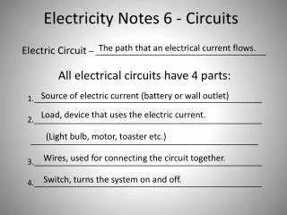
AS Level Electricity - Circuits
AS Level Electricity - Circuits. Taking Measurements. The p.d. across a component in a circuit is measured in volts (V) using a voltmeter connected across (in parallel with) the component. . Taking Measurements.


AS Level Electricity - Circuits
E N D
Presentation Transcript
Taking Measurements • The p.d. across a component in a circuit is measured in volts (V) using a voltmeter connected across (in parallel with) the component.
Taking Measurements • The current (I) flowing through a component in a circuit is measured in amperes (A) using an ammeter connected in series with the component.
Current • A current will flow through an electrical component (or device) only if there is a voltage or potential difference (p.d.) across its ends. • The bigger the potential difference across a component, the bigger the current that flows through it.
Model • You can think of electrical potential as being the topography of the electrical environment. • The flow of charged particles is affected by the steepness of the ‘slope’. • The change in volts per metre is a measure of how steep the slope between two points is… the steeper the ‘potential gradient’ the faster the charge will flow.
Current • An electric current is a flow of charge (Q) measured in coulomb (C). • The charges 'flowing' are usually electrons (in a wire) but can be ions (in a solution).
Current • It is the 'net' flow of charge that makes the current. • Charges going in opposite directions cancel out each other's effect. • Double-charged ions will make double the current that single-charged ones would.
Resistance • Components resist a current flowing through them. • The bigger their resistance, the smaller the current produced by a particular voltage, or the bigger the voltage needed to produce a particular current. • Resistance (R) is measured in ohms (W)
Resistance • When electrical charge flows through a resistor, electrical energy is transferred as heat according to the equation P=IV • This makes components get hotter as current goes through them. • A change in temperature can change the resistance of the component. You need to appreciate this.
Cells and Batteries • An electric cell provides the potential difference for a battery powered circuit by changing chemical energy into electrical energy.
Cells and Batteries • If more than one electrical cell is connected together the term for the power source is ‘battery’ – a single cell is just called an electric cell.
Cells and Batteries • A cell’s potential difference between its terminals has a chemical source and that this can ‘run down’ with use or incorrect storage providing less of an electrical gradient for the current (i.e. the voltage stamped on a battery might not be correct).
Electrical Energy Transfer • As an electric current flows through a circuit, energy is transferred from the battery or power supply to the components in the electrical circuit. • An electric current is a flow of charge. • Charge (Q), measured in coulomb (C) is a property of the electrons that move in the wire. Each electron has a very tiny charge of 1.6 X 10⁻¹⁹C
Equations you should already know from GCSE When electrical charge flows through a resistor, electrical energy is transferred as heat. The rate of energy transfer (power) is given by: P = IV Where: P = power (in watts, W) V = potential difference (in volts, V) I= current (in ampere, A) 1 watt is the transfer of 1J of energy in 1s.
Equations you should KNOW The higher the voltage of a supply, the greater the amount of energy transferred for a given amount of charge which flows. E = VQ Where E = energy transferred (in joule, J) V = potential difference (in volt, V) Q = charge (coulomb, C)
Equations you should KNOW: Q = It Where: Q = charge (coulomb, C) I = current (in ampere, A) t = time (in seconds, s)
Equations you should KNOW V = IR Where: V = potential difference (in volts, V) I= current (in ampere, A) R = resistance (in ohm, W)
Equations you should KNOW E = Pt Where: E = energy transferred (in joule, J) P = power (in watts, W) t = time (in seconds, s)
For all equationsyou should be able to: • recall the equation • manipulate it • know the symbols, values and units • use it in calculations • be able to use S.I. Prefixes with the units
Symbols (cont.) You have to be able to draw these symbols and incorporate them into circuits. They must be drawn carefully. Never put a symbol in a ‘corner’. Never leave a gap. Use a sharp pencil to draw the circuits.
Series Circuits When components are connected in series: • their total resistance is the sum of their separate resistances RTOTAL = R1 + R2 + ..........RN; • the same current flows through each component; • the potential difference from the supply is shared between them.
Parallel Circuits When components are connected in parallel: • there is the same potential difference across each component; • the current through each component depends on its resistance; the greater the resistance of the component, the smaller the current; • the total current through the whole circuit is the sum of the currents through the separate components - this follows from Kirchhoff's First Law - see below.
Characteristic Curves • Current-voltage graphs are used to show how the current through a component varies with the voltage you put across it. • They are called characteristic curves of the components.
The current through an ohmic conductor (e.g. a wire) is proportional to the voltage across the resistor at constant temperature. This is known as Ohm's Law. The straight line shows proportionality – the fact it goes through the origin shows it is directly proportional – double the voltage and the current doubles!
The resistance of a filament lamp increases as the temperature of the filament increases. When the filament is very cool the graph is a straight line – it curves most as the temperature changes rapidly (when it goes through the red glow to white glow stage). When it is really hot it gets to a steady temperature and the line straightens out again.
The current through a diode effectively only flows in one direction only. It acts like a closed switch when connected in forward bias and an open switch when in reverse bias. When connected in forward bias its resistance is very low (provided it has a potential difference of more than 0.6 volts across it). The diode has a very high resistance in the reverse bias therefore only a tiny current flows. Zero p.d. gives zero current.
You also need to KNOW • The resistance of a light dependent resistor decreases as the light intensity increases. • The resistance of a thermistor decreases as the temperature increases. (There are some thermistors which behave in the opposite way to this but all of your questions will be set on this version).