Understanding Internetworking: Key Concepts, Protocols, and Delivery Mechanisms
This chapter delves into the essential aspects of internetworking, focusing on addressing concepts, routing protocols, and the Internet Protocol (IP). It highlights the challenges of connecting heterogeneous and large-scale networks, emphasizing routing efficiency. Various protocols such as ARP, DHCP, and BGP are introduced alongside the importance of IP for enabling a scalable, logical network. The best-effort delivery service model, packet format, and key IP fields are also discussed, providing a comprehensive overview of how data is transmitted across interconnected networks.

Understanding Internetworking: Key Concepts, Protocols, and Delivery Mechanisms
E N D
Presentation Transcript
CHAPTER 4 IINTER NETWORKING Computer Networks-Internetworking
Contents • Addressing concepts- IP • Routing Protocols • ARP, RARP, DHCP, ICMP, RIP, • OSPF, CIDR, BGP • IPv6 Computer Networks-Internetworking
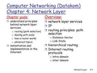
Internetworking • We have seen how to build a single network using point-to-point links, shared media, and switches. • There are two important problems that must be addressed when connecting networks: heterogeneity and scale. • One challenge in internetworking is routing. • How to find an efficient path through a network with millions, or billions, of nodes? Computer Networks-Internetworking
Simple Internetworking (IP) • What Is an Internetwork? • We use the term “internetwork,” or just “internet” with a lowercase i, to refer to an arbitrary collection of networks interconnected to provide some sort of host-to-host packet delivery service. • An internetwork is an interconnected collection of Ethernet, 802.5, ATM….. networks. • An internet is a logical network built out of a collection of physical networks. Computer Networks-Internetworking
An internetwork is often referred to as a “network of networks” because it is made up of lots of smaller networks. • In this figure, we see Ethernets, an FDDI ring, and a point-to-point link. Each of these is a single-technology network. The nodes that interconnect the networks are called routers. They are also sometimes called gateways. Computer Networks-Internetworking
The Internet Protocol is the key tool used today to build scalable, heterogeneous internetworks. • IP runs on all the nodes (both hosts and routers) in a collection of networks and allows these nodes and networks to function as a single logical internetwork. Computer Networks-Internetworking
Service Model • Service model is the host-to-host services that is to be provided over each of the underlying physical networks. • The IP service model have two parts: • An addressing scheme, which provides a way to identify all hosts in the internetwork, and a datagram (connectionless) model of data delivery. • This service model is sometimes called best effort because, although IP makes every effort to deliver datagrams, it makes no guarantees. Computer Networks-Internetworking
Datagram Delivery • The IP datagram is fundamental to the Internet Protocol. • Every datagram carries enough information to let the network forward the packet to its correct destination. • There is no need for any advance setup mechanism to tell the network what to do when the packet arrives. • You just send it, and the network makes its best effort to get it to the desired destination. • If something goes wrong and the packet gets lost, corrupted, misdelivered, the network does nothing—it made its best effort. • This is sometimes called an unreliable service. Computer Networks-Internetworking
Best-effort delivery does not just mean that packets can get lost. • Sometimes they can get delivered out of order, and sometimes the same packet can get delivered more than once. • The higher-level protocols or applications that run above IP need to be aware of all these possible failure modes. Computer Networks-Internetworking
Packet Format • The Version field specifies the version of IP. • The current version of IP is 4, and it is sometimes called IPv4. • HLen, specifies the length of the header in 32-bit words. • Most of the time, the header is 5 words (20 bytes) long. Computer Networks-Internetworking
The 8-bit TOS (type of service) field, its basic function is to allow packets to be treated differently based on application needs. • For example, the TOS value might determine whether or not a packet should be placed in a special queue that receives low delay. • The next 16 bits of the header contain the Length of the datagram, including the header. • The maximum size of an IP datagram is 65,535 bytes. Computer Networks-Internetworking
The second word of the header contains information about fragmentation. • The next byte is the TTL (time to live) field. • The intent of the field is to catch packets that have been going around in routing loops and discard them, rather than let them consume resources indefinitely. • TTL was set to a specific number of seconds that the packet would be allowed to live, and routers along the path would decrement this field until it reached 0. • The value 64 is the current default. Computer Networks-Internetworking
The Protocol field is simply a demultiplexing key that identifies the higher-level protocol to which this IP packet should be passed. • There are values defined for TCP (6), UDP (17) for protocol field. • The Checksum is calculated by considering the entire IP header as a sequence of 16-bit words, adding them up using ones complement arithmetic, and taking the ones complement of the result. • The last two required fields in the header are the SourceAddr and the DestinationAddr for the packet. • Finally, there may be a number of options at the end of the header. • The presence or absence of options may be determined by examining the header length (HLen) field. • Options are used rarely, a complete IP implementation must handle them all. Computer Networks-Internetworking
Fragmentation and Reassembly • An Ethernet can accept packets up to 1500 bytes long, while FDDI packets may be 4500 bytes long. • This leaves two choices for the IP service model: • 1. Make sure that all IP datagrams are small enough to fit inside one packet on any network technology. • 2. Provide a means by which packets can be fragmented and reassembled when they are too big to go over a given network technology. • The central idea here is that every network type has a maximum transmission unit (MTU), which is the largest IP datagram that it can carry in a frame. Computer Networks-Internetworking
When a host sends an IP datagram, it can choose any size that it wants. • A reasonable size is the MTU of the network to which the host is directly attached. • Then fragmentation will only be necessary if MTU is smaller than the IP datagram. • Fragmentation occurs in a router when it receives a datagram and wants to forward over a network that has an MTU smaller than the received datagram. • Fragments will reassemble at the receiving host with the help of same identifier in the Ident field. • This identifier is chosen by the sending host and is unique among all the datagrams that might arrive at the destination. • IP does not attempt to recover from missing fragments. Computer Networks-Internetworking
1. Each fragment is itself a self-contained IP datagram that is transmitted over a sequence of physical networks, independent of the other fragments. 2. Each IP datagram is reencapsulated for each physical network over which it travels. Computer Networks-Internetworking
Global Addresses • We need a global addressing scheme—one in which no two hosts have the same address. • Global uniqueness is the first property that should be provided in an addressing scheme. • Ethernet addresses are globally unique, but that alone does not suffice for an addressing scheme in a large internetwork. • Ethernet addresses are flat, which means that they have no structure and provide very few clues to routing protocols. • In contrast, IP addresses are hierarchical, means they are made up of several parts that correspond to some sort of hierarchy in the internetwork. • IP addresses consist of two parts, a network part and a host part. Computer Networks-Internetworking
The network part of an IP address identifies the network to which the host is attached. • All hosts attached to the same network have the same network part in their IP address. • The host part then identifies each host uniquely on that particular network. • IP addresses are divided into 3 different classes, as shown below. Computer Networks-Internetworking
The class of an IP address is identified in the most significant few bits. • If the first bit is 0, it is a class A address. • If the first bit is 1 and the second is 0, it is a class B address. • If the first two bits are 1 and the third is 0, it is a class C address. • Class A addresses were designed for large organization with a large number of attached hosts or routers. • Class B addresses were designed for midsize organization with ten of thousands of attached hosts or routers. • Class C addresses were designed for small organizations with a small number of attached hosts or routers. • Class D addresses were designed for multicasting. • Class E addresses were reserved for future use. Computer Networks-Internetworking
Class A networks have 7 bits for the network part and 24 bits for the host part. • It means that there can be only 126 class A networks (the values 0 and 127 are reserved), but each of them can accommodate up to 224-2 (about 16 million) hosts. • Class B addresses allocate 14 bits for the network and 16 bits for the host, meaning that each class B network has room for 65,534 hosts. • Finally, class C addresses have only 8 bits for the host and 21 for the network part. • Therefore, a class C network can have only 256 unique host identifiers, which means only 254 attached hosts. • IP addresses are written as four decimal integers separated by dots. • An example of an IP address written as a four decimal integers separated by dots is 171.69.210.245. Computer Networks-Internetworking
Datagram Forwarding in IP • forwardingis the process of taking a packet from an input and sending it out on the appropriate output. • routingis the process of building up the tables that allow the correct output for a packet to be determined. • Forwarding of IP datagrams are as follows: • ■ Every IP datagram contains the IP address of the destination host. • ■ The “network part” of an IP address uniquely identifies a single physical network that is part of the larger Internet. Computer Networks-Internetworking
■ All hosts and routers that share the same network part of their address are connected to the same physical network and can thus communicate with each other by sending frames over that network. ■ Every physical network that is part of the Internet has at least one router, & this router can exchange packets with hosts or routers on either network. R2 R1 N/W Computer Networks-Internetworking
We can describe the datagram forwarding algorithm in the following way: if (NetworkNum of destination = NetworkNum of one of my interfaces) then deliver packet to destination over that interface else if (NetworkNum of destination is in my forwarding table) then deliver packet to NextHop router else deliver packet to default router For a host with only one interface and only a default router in its forwarding table, this simplifies to if (NetworkNum of destination = my NetworkNum) then deliver packet to destination directly else deliver packet to default router Computer Networks-Internetworking
Address Translation (ARP)(Logical to Physical) • We know how to get IP datagrams to the right physical network, but the issue is how to get a datagram to a particular host orrouter on that network. • The main issue is that IP datagrams contain IP addresses, but the physical interface hardware on the host or router to which you want to send the datagram only understands the addressing scheme of that particular network. • Whenever a host or a router has an IP datagram to send to another host or router, it has the logical (IP) address of the receiver. • Thus, we need to translate the IP address to a link-level address that makes sense on this network. (Ex: 48 bit Ethernet address) Computer Networks-Internetworking
We can then encapsulate the IP datagram inside a frame that contains that link-level address and send it either to the ultimate destination or to a router that promises to forward the datagram toward the ultimate destination. • One simple way to map an IP address into a physical network address is to encode a host’s physical address in the host part of its IP address. (has a drawback) • A more general solution would be for each host to maintain a table of address pairs; that is, the table would map IP addresses into physical addresses. • While this table could be centrally managed by a system administrator and then copied to each host on the network Computer Networks-Internetworking
A better approach would be for each host to dynamically learn the contents of the table using the network. This can be accomplished using the Address Resolution Protocol (ARP). • The goal of ARP is to enable each host on a network to build up a table of mappings between IP addresses and link-level addresses. • Since these mappings may change over time, the entries are timed out periodically and removed. This happens on the order of every15 minutes. The set of mappings currently stored in a host is known as the ARP cache or ARP table. • Suppose if a host wants to send an IP datagram to a host/router which is on the same network, it first checks for a mapping in the cache. • If no mapping is found, it needs to invoke the Address Resolution Protocol over the network. Computer Networks-Internetworking
It does this by broadcasting an ARP query onto the network. This query contains the target IP address. • Each host receives the query and matches its IP address. If it does match, the host sends a response message that contains its link-layer address back to the originator of the query. • The originator adds the information contained in this response to its ARP table. • The query message also includes the IP address and link-layer address of the sending host. Thus, when a host broadcasts a query message, each host on the network can learn the sender’s link-level and IP addresses and place that information in its ARP table. • Not every host adds this information to its ARP table. If the host already has an entry for that host in its table, it “refreshes” this entry. Computer Networks-Internetworking
Figure shows the ARP packet format for IP-to-Ethernet address mappings. Computer Networks-Internetworking
■ a HardwareType field, which specifies the type of physical network (e.g., Ethernet) ■ a ProtocolType field, which specifies the higher-layer protocol (e.g., IP) ■ HLen (“hardware” address length) and PLen (“protocol” address length) fields, which specify the length of the link-layer address and higher-layer protocol address, respectively ■ an Operation field, which specifies whether this is a request or a response ■ the source and target hardware (Ethernet) and protocol (IP) addresses Computer Networks-Internetworking
Host Configuration (DHCP) • IP addresses not only must be unique on a given internetwork, but also must reflect the structure of the internetwork. • It is not possible for the IP address to be configured once into a host when it is manufactured. • In addition to an IP address, there are some other information that a host needs to have before it can start sending packets. • The most notable of these is the address of a default router. • Most host operating systems provide a way for a system administrator or a user, to manually configure the IP information needed by a host. Computer Networks-Internetworking
However, there are some obvious drawbacks to such manual configuration. • First is that it is simply a lot of work to configure all the hosts in a large network directly. • Second is the configuration process is very error-prone, since it is necessary to ensure that every host gets the correct network number. • For these reasons, automated configuration methods are required. The method uses a protocol known as the Dynamic Host Configuration Protocol (DHCP). • There is at least one DHCP server for an administrative domain responsible for providing configuration information to hosts. Computer Networks-Internetworking
The DHCP server can function just as a centralized repository for host configuration information. • DHCP avoids the n/w admin from having to walk around every host in the company with the list of addresses and configure them manually. • The configuration information stored in the DHCP server is automatically retrieved by each host when it is booted or connected to the network. • The configuration information for each host is stored in a table that is indexed by “hardware address” Computer Networks-Internetworking
A more sophisticated use of DHCP saves the network administrator from even having to assign addresses to individual hosts. • Here, the DHCP server maintains a pool of available addresses that it hands out to hosts on demand. • The first problem faced by DHCP is that of the server discovery. • To contact a DHCP server, a newly booted or attached host sends a DHCPDISCOVER message to a special IP address (255.255.255.255) that is an IP broadcast address. • This means it will be received by all hosts and routers on that network. • In the simplest case, one of these nodes is the DHCP server for the network. The server would then reply to the host that generated the discovery message. Computer Networks-Internetworking
Having a DHCP server on every n/w creates potentially large number of servers that need to be configured. • Thus DHCP uses the concept of a relay agent. • There is at least one relay agent on each network, and it is configured with just one piece of information: the IP address of the DHCP server. • When a relay agent receives a DHCPDISCOVER messasge, it sends it to the DHCP server & awaits the response and then send back to the requesting client. Computer Networks-Internetworking
DHCP is derived from an earlier protocol called BOOTP, and some of the packet fields are thus not strictly relevant to host configuration. • When trying to obtain configuration information, the client puts its hardware address (e.g., its Ethernet address) in the ciaddr field. • The DHCP server replies by filling in the yiaddr (“your” IP address) field and sending it to the client. Computer Networks-Internetworking
In the case where DHCP dynamically assigns IP addr to hosts, hosts cannot keep addresses indefinitely. • At the same time, a host could not give back its address, since it might have crashed, been unplugged from the network, or been turned off. • Thus, DHCP allows addresses to be “leased” for some period of time. • Once the lease expires, the server is free to return that address to its pool. • A host with a leased address clearly needs to renew the lease periodically if it is still connected to the network and functioning correctly. Computer Networks-Internetworking
Error Reporting (ICMP) • when a router does not know how to forward the datagram or when one fragment of a datagram fails to arrive at the destination—it does not necessarily fail silently. • IP is always configured with a companion protocol, known as the Internet Control Message Protocol (ICMP). • It defines a collection of error messages that are sent back to the source host whenever a router or host is unable to process an IP datagram successfully. • ICMP also defines a handful of control messages that a router can send back to a source host. • One of the most useful control messages, called an ICMP-Redirect, tells the source host that there is a better route to the destination. Computer Networks-Internetworking
Virtual Networks and Tunnels • So far we have discussed for unrestricted communication. • This is usually the goal in the Internet. • However, there are many situations where more controlled connectivity is required. An important example of such a situation is the virtual private network (VPN). • Corporations with many sites often build private networks by leasing transmission lines from the phone companies and using those lines to interconnect sites. • In such a network, communication is restricted to take place only among the sites of that corporation, which is often desirable for security reasons. Computer Networks-Internetworking
To make a private network virtual, the leased transmission lines— which are not shared with any other corporations—would be replaced by some sort of shared network. • A virtual circuit is a very reasonable replacement for a leased line because it still provides a logical point-to-point connection between the corporation’s sites. • For example, if corporation X has a VC from site A to site B, then clearly it can send packets between sites A and B. • But there is no way that corporation Y can get its packets delivered to site B without first establishing its own virtual circuit to site B. Computer Networks-Internetworking
In the above figure a Frame Relay or ATM network is used to provide the controlled connectivity among sites. • It is also possible to provide a similar function using an IP network to provide the connectivity. • We cannot just connect the various corporations’ sites to a single internetwork because that would provide connectivity between corporation X and corporation Y. • To solve this problem, we use a concept called the IP tunnel. Computer Networks-Internetworking
We can think of an IP tunnel as a virtual point-to-point link between a pair of nodes that are actually separated by an arbitrary number of networks. • The virtual link is created within the router at the entrance to the tunnel by providing it with the IP address of the router at the far end of the tunnel. • Whenever the router at the entrance of the tunnel wants to send a packet over this virtual link, it encapsulates the packet inside an IP datagram. • The destination address in the IP header is the address of the router at the far end of the tunnel, while the source address is that of the encapsulating router. Computer Networks-Internetworking
Reasons for tunnelling: • One reason is security. • Second reason may be that R1 and R2 have some capabilities that are not widely available in the intervening networks, such as multicast routing. • A third reason to build tunnels is to carry packets from protocols other than IP across an IP network. • Tunneling does have its downsides. • One is that it increases the length of packets, causes BW wastage. • There may also be performance implications for the routers at either end of the tunnel, as they add and remove the tunnel header. • There is a management cost for the administrative entity that is responsible for setting up the tunnels and making sure they are correctly handled. Computer Networks-Internetworking
Routing • In the case of virtual circuits, routing is an issue only for theconnection request packet; all subsequent packets follow the same path as the request. • In datagram networks, including IP networks, routing is an issue for every packet. • In either case, a switch or router needs look to at the packet’s destination addr and then to determine which of the output ports delivers the packet to that address. Computer Networks-Internetworking
The forwarding table contains the mapping from a network number to an outgoing interface, MAC info such as Ethernet address of the next hop. • Routing table is built up by the routing algorithms as a precursor to building the forwarding table. • Routing table contains mappings from network number to next hops and also contain how this info was learned. Computer Networks-Internetworking
The forwarding table needs to be structured to optimize the process of looking up a network number while forwarding a packet. • Routing table needs to be optimized for the purpose of calculating changes in topology. Computer Networks-Internetworking