Light, Reflection, and Refraction
Light, Reflection, and Refraction. Chapters 14 and 15 OPTICS. Electromagnetic Waves. Magnetic field wave perpendicular to an electric field wave All objects emit EMWs. Temp EMW Electromagnetic spectrum Range of all frequencies of light

Light, Reflection, and Refraction
E N D
Presentation Transcript
Light, Reflection, and Refraction Chapters 14 and 15 OPTICS
Electromagnetic Waves • Magnetic field wave perpendicular to an electric field wave • All objects emit EMWs. • Temp EMW • Electromagnetic spectrum • Range of all frequencies of light • Visible light is a very small portion of that entire spectrum.
c • Speed of Light - 3.00 x 10⁸m/s. • = (wavelength) x (frequency) • c = ƒ
Example • AM Radio waves • 5.4 x 10⁵ Hz • 1.7 x 10⁶ Hz • = ?
Visible Light • Part of the EMS humans can see • Red - 750nm (x10-9m) • Purple - 380nm • Bees, Birds – UV • Snakes – IR
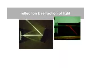
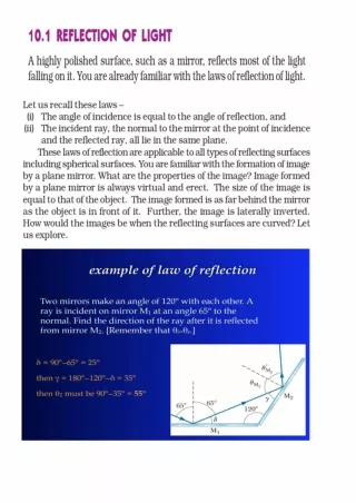
Reflection • Light waves usually travel in straight paths • Change in substance changes direction • Opaque - does not permit light • some light reflected • some light absorbed as heat
Reflection • Texture affects reflection • Diffuse reflection (rough) • reflects light in many different directions, • Specular reflection (smooth) • reflects light in only one direction • Smooth – variations in surface
Mirrors • Light striking a mirror reflects at the same angle that it struck the mirror
Flat Mirrors • p = q • p- objects distance to the mirror • q - distance from the mirror to the image • Virtual image • Does not exist • Made by our eyes
Ray Diagrams • Used to predict the location of the image of an object
Concave Spherical Mirrors • Reflective surface is on the interior of a curved surface • C – center of curvature • R – Radius (distance to C) • f – Focal Point (1/2 R) • Principal axis • any line that passes through C • usually oriented with an object
Mirror Equations • 1/object distance + 1/image distance = 1/focal length 1/p + 1/q = 1/f • Magnification (M) = Image height/object height (h / h) - (q / p) • M = h / h = - (q / p)
Concave Spherical Mirror Rules • A ray traveling through C will reflect back through C • A ray traveling through (f) will reflect parallel to the PA • A ray traveling to the intersection of the PA and the mirror will reflect at the same angle below the PA. • A ray traveling parallel to PA will reflect through the focal point
Ray Diagrams • Draw three rays • The image forms at the point of intersection • Example • f = 10.0cm • p = 30.0cm • h = 3.00cm
Convex Spherical Mirrors • Reflective surface is on the outside of the curve. • The points f and C are located behind the mirror • negative
Rules • A ray parallel to the PA will reflect directly away from f. • A ray towards f will reflect parallel to the PA • A ray towards C will reflect directly away from C. • A ray to the intersection of PA and mirror will reflect at the same angle below the OA. • Trace the 3 diverging lines back through the mirror to reveal the location of the image which is always virtual
Example • f = -8.00cm • p= 10.0cm • h = 3cm
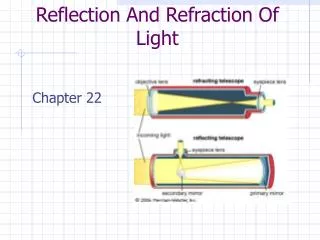
Parabolic Mirrors • Rays that hit spherical mirrors far away from the OA often reflect though other points causing fuzzy images, spherical aberration. • Telescopes use parabolic mirrors as they ALWAYS focus the rays to a single point.
Refraction • Substances that are transparent or translucent allow light to pass though them. • Changes direction of light • Due to the differences in speed of light
Analogy • A good analogy for refracting light is a lawnmower traveling from the sidewalk onto mud
Index of Refraction (n) • The ratio of the speed of light in a vacuum to the speed of light in a medium • n - c
Snell’s Law • ni(sini) = nr(sinr) • r = sin-1{(ni/ nr)(sini)} • Example • i = 30.0⁰ • ni = 1.00 • nr = 1.52
i = 30.0⁰ • ni = 1.00 • nr = 1.52
Total Internal Reflection • If the angle of incidence of a ray is greater than a certain critical angle the ray will reflect rather than reflect • This principal is responsible for the properties of fiber optic cables. • Remember the lawn mower analogy…
Critical Angle • sin Θc = nr / ni • As long as nr < ni • What is the critical angle for light traveling from Diamond to Air?
nr = 1.000 ni = 2.419
Thin Lenses • Converging • Diverging • f- curve of lens & index of refraction
Converging Lens Diagram • Ray parallel to PA, refracts through far focal point • Ray through center of lens, continues straight line • Ray through near focal point, refracts through lens, continues parallel to PA • Treat lens as though it were a flat plane.
Diverging Lens Diagram • Because the rays that enter a diverging lens do not intersect a virtual image is formed by tracing back the refracted rays. • Ray 1 - parallel to PA, refracts away from near f, trace back to near f. • Ray 2 - ray toward far f, refracts parallel to PA, trace back parallel to PA • Ray 3 - ray through center, continues straight, trace back toward object
Converging Lens Example • p = 30.0cm • f = 10.cm
Diverging Lens Example • p = 12.5cm • f = -10.0cm