Piping Diagram for Bulkhead Rupture and Backflow Preventer Systems
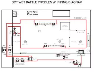
This document outlines the detailed piping diagram for the bulkhead rupture systems, incorporating various components such as CW (Cooling Water) and FPL (Fire Protection Line). It includes key references for valve placements and backflow preventers, ensuring system integrity and safety. The diagram facilitates a comprehensive understanding of the operational flow and critical connections, aiding in maintenance and emergency response scenarios. It serves as an essential resource for engineering teams involved in troubleshooting and system design.

Piping Diagram for Bulkhead Rupture and Backflow Preventer Systems
E N D
Presentation Transcript
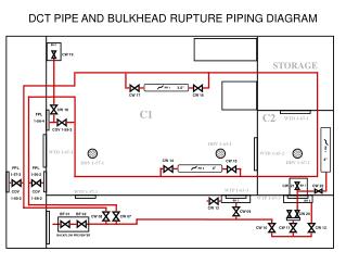
PR 1 PR 1 PR 2 DCT PIPE AND BULKHEAD RUPTURE PIPING DIAGRAM BH 1 CW 19 3.5” CW 17 CW 16 CW 18 FPL 1-56-4 COV 1-59-2 4” CW 14 CW 15 FPL 1-57-2 FPL 1-56-2 4” CW 21 CW 22 BH 1 COV 1-60-2 COV 1-59-2 BH 2 BH 2 CW 13 CW 09 CW 20 BF 01 BF 02 CW 08 CW 07 CW 12 CW 11 CW 10 BACKFLOW PREVENTER