Download
1 / 19
280 likes | 815 Vues
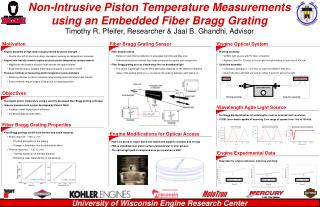
Fiber Bragg Grating (FBG) Sensors For Micromegas. S. Campopiano , A. Iadicicco (University of Naples “Parthenope ”) M. Della Pietra (University of Naples “Parthenope” and INFN sez Naples) V. Canale , P. Iengo (INFN sez. Naples and University of Naples “Federico II”). Outline.

E N D
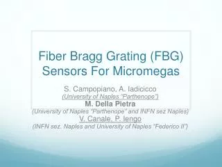
Fiber Bragg Grating (FBG) Sensors For Micromegas S. Campopiano, A. Iadicicco (University of Naples “Parthenope”) M. Della Pietra (University of Naples “Parthenope” and INFN sez Naples) V. Canale, P. Iengo (INFN sez. Naples and University of Naples “Federico II”)
Outline • FBG sensors • Previous experience in HEP • Experimental setup • Preliminary results • Plan for next measurements
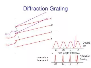
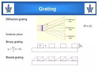
FBG sensors • A sensor based on Fiber Bragg Grating is an optical fibre where the refractive index in the fibre's core has an induced period variation, in such a way to produce a “grating” on which the light undergoes the Bragg diffraction. • In this way the reflected spectrum has a peak centred on a wavelength λB that is a function of Λ, the period of the refraction index changing
FBG sensors • With more details, if the period of refraction changes due to an external strain ε and/or a temperature variation ΔT, the Bragg wavelength changes according to the law:
FBG sensors • Clearly the strain ε could be due both to an external mechanical stress and to a temperature change. • Two sensors (one mechanically coupled and the other not) are usually used to disentangle the two effects
FBG sensor in HEP • These sensors have a wide use in many fields, such as industry, space technology, healthcare, civil nuclear industry • Their performance are similar to strain gauge with the advantage that: • many FBG sensors can be installed on the same fiber and can be read out at once; • FBG sensors are insensitive to environmental electromagnetic fields. • FBG sensors can be distributed over a long range system (up to few tens of kilometres)
FBG sensor in HEP • Since few years there is big interest in these optical fiber sensors in the High Energy Physics community for several reasons: • Well know radiation hardness behaviour of the fibers • No sensitivity to external electromagnetic fields • Tiny dimension of the sensors (few hundreds of microns) • Many sensors can be implemented on the same fiber and can be readout simultaneously in an easy way • Strain and temperature sensors have been installed in CMS since 2010 • Temperature monitoring for the Tracker • Strain monitoring for the very forward calorimeter detector • A lot of R&D is ongoing to develop humidity, chemical radical and B-Field sensors with the same technique
FBG on micromegas • Try to understand if we can use these sensor as a monitor of the deformation of the detector. • This technique is complementary to the alignment system. • Very preliminary work done using FBG on the MM support panel ( 2nd gluing trial in Rome 1 lab) • FGBs used both as strain and temperature sensor • Deformation on the panel induced by bending it under pressure of a known weight.
Experimental setup Light source (SLED – 2 mW) FBG Optical coupler 2x1 50% Optical Spectrum Analizer
Experimental setup SLED Source Optical coupler
Experimental setup Source spectrum Reflection from FBG spectrum OSA with a single point resolution of 20 pm
Experimental setup FBG sensor glued on the support plane Glue is the commercial loctite Fiber dimension is 125 micron
Experimental setup FBG sensor is glued on the bottom surface Load is applied on the top one
Preliminary results Load Unload Load again
Preliminary results L s L + δ FBG sensor Good agreement with a simple model: Panel is bent as an arc Strain is uniform over the surface
Preliminary results FBG Temp FBG Strain Ext Temp • All night long data taking with no load on the panel: • Strain (blue curve) is only due to thermal expansion • 120 pm of shift corresponds to about 5 degrees in T
Work in progress • More data taking in different condition; • Measurement of strain in both coordinates; • Measurement of planar deformation by the difference of strains measured on both sides of the panel; • Correction of thermal strain by temperature variations • Try to glue the fiber with the correct glue • Need a mechanical simulation to understand the right number of sensors and their position on the detector.