Download
1 / 16
160 likes | 302 Vues
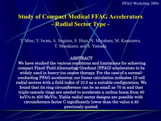
FFAG Workshop 2004. Study of Compact Medical FFAG Accelerators - Radial Sector Type - T. Misu, Y. Iwata, A. Sugiura, S. Hojo, N. Miyahara, M. Kanazawa, T. Murakami, and S. Yamada. ABSTRACT

E N D
FFAG Workshop 2004 Study of Compact Medical FFAG Accelerators - Radial Sector Type - T. Misu, Y. Iwata, A. Sugiura, S. Hojo, N. Miyahara, M. Kanazawa, T. Murakami, and S. Yamada ABSTRACT We have studied the various conditions and limitations for achieving compact Fixed-Field Alternating-Gradient (FFAG) accelerators to be widely used in heavy-ion cancer therapy. For the case of a normal-conducting FFAG accelerator, our linear calculation indicates 12-cell radial sectors with a field index of 10.5 as a suitable configuration. We found that its ring circumference can be as small as 70 m and that triple-cascade rings are needed to accelerate a carbon beam from 40 keV/u to 400 MeV/u. Viable radial-sector designs are possible with circumference factor C significantly lower than the value 4.45 previously quoted.
FFAG Workshop 2004 Widespread Use of Carbon-Beam Radio-Therapy The Heavy Ion Medical Accelerator in Chiba (HIMAC) has shown the therapy’s effectiveness after treating over 1800 patients. However, such carbon-beam medical accelerators are rather large in size and expensive, which prohibit the widespread use of carbon-beam radiotherapy. Therefore, there is a need to develop medical carbon-beam accelerators, that are compact, low-cost and simple to operate. <Potential Advantages of FFAGs over Conventional Synchrotrons> Since the fixed field of FFAG allows a higher magnetic field than synchrotrons, a more compact design may be achieved. The higher repetition rate of FFAG is expected due to its time-independent field structure. With such a high repetition rate, one may expect much shorter irradiation time by increasing beam intensity and a highly controlled delivery of the dose when using the latest irradiation techniques such as the spot-scanning method.
FFAG Workshop 2004 ~ 42 m ~ 65 m ~ 120 m HIMAC at NIRS
FFAG Workshop 2004 ParticleC4+(Injection), C6+(Extraction) Energy40 keV/u - 400MeV/u # of Particles 2 x 10⁹ pps Repetition Rate200Hz FFAG Basic Parameters Constraints ● a maximum magnetic field of 1.9 T ● a ring circumference of 70 m or less (Circumference Factor C of 3.3 or less) ·●an orbit excursion of 1 m or less ● a length of straight section per cell of 1 m or more
FFAG Workshop 2004 Analysis with Linear Optical Model Circumference Factor
FFAG Workshop 2004 KEK 150MeV FFAG NIRS Design Previously quoted theoretical minimum value by Symon et al., Phys. Rev. Vol. 103, 1837 (1956) Comparison of Stability Regions (All solutions are shown.) Cell Number : 12 (a) Singlet (b) Doublet (c) D-F-D Triplet 5 4 3 2 1 1st Stability Region 1st Stability Region 1st Stability Region 2nd Stability Region 2nd Stability Region 2nd Stability Region Circumference Factor C 0 20 40 60 80 0 20 40 60 80 0 20 40 60 80 100 Field Index k
FFAG Workshop 2004 Stability Regions of Radial-Sector Doublet FFAGs (N=8) (All solutions are shown.) 20.04 13.36 6.68 1st Stability Region E=400MeV/u Bmax=1.9T 16.70 10.02 3.34 2nd Stability Region Circumference Factor 3rd Stability Region Ring Radius at Bmax=1.9T (m) |by | (m) 2nd Stability Region 1st Stability Region For higher order stability regions (phase advance>180°), b function becomes large. Although radial-sector lattices residing in higher order stability regions are “interesting”, they are regarded as “questionable” configurations. Feasibility study of 1st order stability regions only
FFAG Workshop 2004 2.0 2.0 3.0 3.0 4.0 4.0 4.0 3.0 C = 3.3 2.0 NIRS Design 1st Stability Region of Radial-Sector Doublet FFAGs (All solutions are shown.) N=12 N=16 N=8 15 10 5 0 RingRadius (m) 0 5 10 15 20 5 10 15 20 5 10 15 20 Field Index k Bmax = 1.9 T ・Large k and small ring radius are preferred. ・Minimum radii increase with field index k. ・To find parameters satisfying ring radius < 11 m and small orbit excursion, we chose N = 12.
FFAG Workshop 2004 Orbit Excursion vs. Drift Length of Radial-Sector Doublet FFAGs (Only solutions with radius < 11m are shown.) Momentum Ratio: 2.0 Momentum Ratio: 3.0 Momentum Ratio: 4.0 3 2 1 0 Drift Length per Cell (m) 0 1 0 1 0 1 2 Orbit Excursion (m)
FFAG Workshop 2004 LE-FFAGME-FFAGHE-FFAG ParticleC4+ C6+ C6+ Energy (MeV/u) 0.04-6 6-100 100-400 Cell Number 10 12 12 Periodicity 5 12 12 Field Index k 6.5 10.5 10.5 Extraction Radius (m)2.766.3410.21 Orbit excursion(m) 0.764 0.769 0.681 F/D 1.35/1.61 1.45/1.45 1.93/1.93 Normal-Conducting Radial-Sector FFAG Configuration 10 5 0 LE-FFAG 0 20 40 60 80 20 10 30 20 10 0 ECR ME-FFAG ~20.5 m b (m) ECR 1st FFAG 2nd FFAG HE-FFAG 0 10 20 30 Angle (deg.)
FFAG Workshop 2004 Technical Concerns 1. Possibility of achieving a broad-band high accelerating gradient rf cavity LE-FFAG: 0.22 – 1.88 MHz, 3.3 kV ME-FFAG: 0.89 – 3.00 MHz, 18.4 kV HE-FFAG: 1.99 – 3.10 MHz, 45.5 kV 2. Tune shift due to the fringing field LE-FFAG: momentum ratio of 12.27 ME-FFAG: momentum ratio of 4.18 HE-FFAG: momentum ratio of 2.15 3. Dynamic aperture of each ring LE-FFAG: beam emittance of 108 p mm-mrad ME-FFAG: beam emittance of 8.8 p mm-mrad HE-FFAG: beam emittance of 2.1 p mm-mrad
Parameter LE-FFAG ME-FFAG HE-FFAG FFAG Workshop 2004 Number of Cavities 1 2 4 Number of Cores per Cavity 4 10 20 25 Shunt Impedance per Cavity [kW] 0.34 1.22 2.86 R570 800 Total Power [kW] 20 90 180 R70 (unit: mm) Estimation of Cavity Parameters using FINEMET 600 400 200 0 -200 -400 Cavity Impedance (W) 0 1 2 3 4 5 Frequency (MHz)
FFAG Workshop 2004 Estimation of Vertical Tune Shift due to Fringing Field – LE-FFAG - 2.5 2.0 1.5 1.0 0.5 Injection Vertical Tune Since gradient-field production by pole gap variation is the cause of tune shift, hybrid-type magnets, which produce radial gradient field by combining both coil-current distribution and magnetic pole gap, may be considered. Extraction 2.0 2.1 2.2 2.3 2.4 2.5 2.6 2.7 2.8 2.9 3.0 Average Orbit Radius (m)
FFAG Workshop 2004 (a) LE-FFAG (b) ME-FFAG (c) HE-FFAG 0.00 -0.15 0.06 0.00 -0.08 -0.20 Wx=2069 pmm-mrad Wx=107 pmm-mrad Wx=1789 pmm-mrad Wx=147 pmm-mrad Injection Wx=198 pmm-mrad Wy=108 pmm-mrad Wy=10 pmm-mrad Wy=10 pmm-mrad x’ (rad) 1.91 1.99 5.74 5.86 9.87 9.97 0.06 0.00 0.00 -0.15 -0.08 -0.20 Wx=130 pmm-mrad Wx=197 pmm-mrad Wx=1789 pmm-mrad Wx=1789 pmm-mrad Extraction Wx=1827 pmm-mrad Wy=10 pmm-mrad Wy=10 pmm-mrad Wy=10 pmm-mrad 2.67 2.77 6.54 6.60 10.56 10.66 x (m) Dynamic Aperture Transmission rate in the LE-FFAG ring was estimated as 20 percent.
FFAG Workshop 2004 Design Summary • In this study, some of the stability regions were surveyed to search for the appropriate cell number N that gives the maximum value of k, while keeping the ring circumference less than 70 m. • (2) Viable radial-sector designs are possible with circumference factors C significantly lower than the value 4.45 previously quoted. • (3) Our preliminary design shows a radial-sector doublet FFAG consisting of triple-cascade rings, in each of which the orbit excursion is kept below 80 cm. • A ring circumference of 69.2 m (corresponding to C = 3.3), which we believe is nearly the optimum size for the radial-sector type, is realized with normal conducting magnets of 1.93 T. • (roughly the same size as the compact synchrotron design) Considering compactness and cost, the radial-sector FFAG design do not show its clear advantage over the compact synchrotron design. However, one of its merits, “high repetition rate”, can give the possible advantages over synchrotrons. Therefore, the further improvements of the cavity performance have been mainly pursued as a key to achieve “high repetition rate”.
FFAG Workshop 2004 Improvements of Cavity Performance - R&D - • Estimation of Core Impedance • - Shape-dependence and size-dependence of core impedance were determined. • - Impedance of racetrack-shape core is greater than that of circular-shape core. • Development of Viable Cooling Methods • - “One-side” (indirect) water-cooling method was employed to keep cavity’s • impedance high. • - Cooling and endurance tests have been performed. • - Indium-bonding method was successfully tested (still expensive). • - Inexpensive “one-side” cooling methods are further investigated. [underway] • (3) Investigating the influence of fringing field [omitted] • - Cavity’s impedance is often influenced by the presence of fringing field, especially in tight lattice structure. • - Avoid the reduction of shunt impedance by taking into account the influence appropriately. • (4) Development of New MA Cores [underway] • - Reduce rf power and/or number of cores by increasing core permeability.