Download
1 / 33
330 likes | 465 Vues
CLIC detector study and status of the CDR process. Lucie Linssen Introduction CLIC_SiD detector geometry and simulation model for the CDR Preparations for the CDR Outstanding issues Outlook http://lcd.web.cern.ch/LCD/ Many thanks to Christian Grefe , Hubert Gerwig and others.

E N D
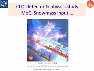
CLIC detector study and status of the CDR process Lucie Linssen Introduction CLIC_SiD detector geometry and simulation model for the CDR Preparations for the CDR Outstanding issues Outlook http://lcd.web.cern.ch/LCD/ Many thanks to Christian Grefe, Hubert Gerwig and others
Other CLIC-related talks Further CLIC-related talks at this workshop: Peter Speckmayer: • Software development and performance studies of CLIC-SiD Norman Graf + Jeremy McCormick: • Software framework + SLiCPandora Tim Barklow: • Generation of physics and beam-background events + Physics benchmarks for CLIC Phil Burrows: • CLIC MDI Harry Weerts • ILC/CLIC SiD synergies, R&D plans
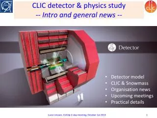
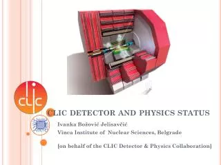
CLIC_SiD overview Size of yoke adapted to coil radius + field saturation. New yoke instrumentation layout FF QD0, BeamCal, BPM and kicker, Lumical, ECAL plug => all supported from tunnel wall B-field 5T, inner bore radius 2740 mm Si/W ECAL and tungsten-based HCAL barrel, steel-based HCAL endcap 6 m These rings are for self-shielding at the IP location Inner radius of vertex detector at 27 mm radius; Adaptation of forward disks
CLIC_SiD Numbers Hubert Gerwig, Nicolas Siegrist
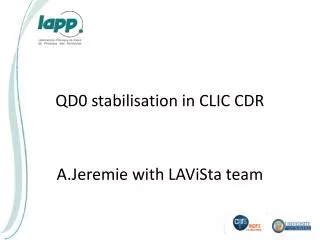
Final focus stabilization Accelerator tunnel side Experiment side Final focus stabilisation to ~0.1 nm required Achieved with combination of active and passive elements
QD0 stabilization • Pre-isolator: • Low dynamic stiffness + large mass (50-100 ton) => Acts as a low-pass filter • Active stabilizator • Piezo-based active stabilizators • Beam-based stabilization • Beam-Position Monitor + Kicker =1 Pre-isolator alone: Response to vertical excitation Frequency
Response to vibration 2.2 nm Vertical groundmotionat CMS. 0.1 nm X Y Z 4 Hz Reduction in r.m.s. displacements by a factor 20 above 4 Hz 12
Vertex Detector & Forward Region • Crossing angle: 20 mrad (14 mrad @ ILC) • Beam-beam interactions produce photons and e+e- pairs • coherent pairswith high energies and low angles (~108/BX) • incoherent pairs with high angles and low energies (~300k per BX) E Θ • Move beam pipe and first vertex layer to ~27 mm to reduce direct hits from pair background • Increase outgoing beam pipe radius to 10 mrad (rmin BeamCal) • Allow space for intra-train-feedback-system and kickers between BeamCal and QD0 # André Sailer E
Occupancy in vertex detector CDR choice Fe 4 mm Hit density (1/(BX mm2) in the vertex detector as a function of the radius of the inner layer (CLIC_ILD study) Back-scattered hits (1/(BX mm2) into the vertex detector (1st layer at 31 mm) as a function of material/thickness of conical beam pipe (CLIC_ILD study) André Sailer
CLIC_SiD Vertex Detector • 0.5 mm Be beam pipe with rmax = 25 mm • removed titanium coating inside beam pipe • 5 pixel layers in barrel (zmax = 100 mm) • 7 pixel disks in endcap and forward • 20*20 µm² pixels with digital readout • 50 µm Sithickness + 130µm Carbon support per double layer (0.12% X0) • Conicalpart of beampipe in 4 mm steel to absorbback-scattering Dominik Dannheim
CLIC_SiD Forward Region “almost” pointing beam pipe to avoid passing material in a shallow angle LumiCal: • implemented like ECal • 20*2.7 mm + 10*5.4 mm layers tungsten • 1 mm gap size (0.3 mm Si + Air, Copper Capton), 3.5*3.5 mm² readout • moved LumiCal behind ECal to avoid gap BeamCal: • 50*2.7 mm tungsten + 1mm gap size • increase outgoing beam pipe opening to 10 mrad • ~50 cm space for kicker and intra-train-feedback between BeamCal and QD0 (L*=3.5 m) ECal Tungsten Cone Mask LumiCal BeamCal Christian Grefe
CLIC_SiD Tracker • 5T solenoid field • 5 barrel strip layers (10cm * 25µm with 50µm digital readout) • 4 endcap stereo strip layers (10cm) * 25µm with 50µm digital readout)
CLIC_SiD Calorimeters • ECal (12 sides) • Absorbers: • 20*2.5 mm tungsten absorber layers • 10*5.0 mm tungsten absorber layers • Active: • 1.25 mm gap size (0.3 mm Si + Air, Copper Capton), 3.5*3.5 mm² readout • HCal (12 sides, 7.5 Λi) • Barrel: 75*10 mm tungsten • Endcap: 60*20 mm steel • Active: 6.5 mm gap size (5 mm polystyrene + 1.5 mm air), 3*3 cm² cell size HCal ECal LumiCal BeamCal HCal Coil • Analog readout for the HCal was chosen as a baseline for CDR simulationmodel • Alternative technologies will be investigated in dedicated studies and presented in the CDR ECal
CLIC_SiD Muon System & Yoke • Yoke (8 sides) • Absorber: 18*10 cm steel • Active: 4cm gap size (RPC 3*3 cm²) • Barrel: 20 cm steel layer after first active layer to take stresses • Yoke Plug (12 sides) • Introduced in order to align start of yoke in the endcap with end of the conductor • instrumented with first muon chamber: 15 cm steel + 4 cm RPC + 9 cm steel Yoke Coil HCal Yoke Plug Yoke HCal Yoke plug layout Coil
Studies of yokeinstrumentation Choose active layers during digitization • First 3 layers are used as a tail catcher • Simulations indicate that2 * 3 layers in addition providegood Muon ID Muon ID processorbeingimplemented in Pandora Based on matchingtrackswithhits in theyokeinstrumentation solenoid hcal Muons in b-jets Efficiency Purity Erik van der Kraaij
CLIC schedule Aug. 2011 CDR document ready
CLIC CDR document schedule CDR deadlines: • Oral presentation to CERN Scientific Policy Committee (SPC) => June 20/21 2011 • Ask SPC to appoint a sub-committee for receiving the document • Allow some time for SPC comments before Dec-2011 CERN council meetings • Our deadline for the completed Vol 3 document: end-August 2011 • Final presentation of printed version to CERN council in December 2011 The oral presentation in June 2011 puts additional constraints on the work plan: • End-May 2011 => all essential input material for the CDR has to be available • End-June 2011 => final deadline of individual chapters • End-August 2011 => deadline for the finished Vol 3 document • End-August 2011 => deadline for the finished Vol 1 document
Planning physics/detector CDR Performance/benchmark simulations are the most critical part for the physics/detector CDR Current time-line for readiness for mass production: • 25/10/2010: Finalize geometry for CLIC_ILD and CLIC_SID • 01/11/2010: Finalize Mokka and SLiC implementations of CLIC_ILD and CLIC_SID • 01/11/2010: Complete implementations of Overlay processor => good progress • 01/12/2010: Complete validation reconstruction path for CLIC_ILD and CLIC_SID • 15/12/2010: Finalize reconstruction software and tag releases CDR editing: Discussions have taken place will editors of of all chapters We now have an almost complete “bullet CDR”
Outstanding issues Recent progress on SiD tracking software for CLIC and on SLiCPandora. Let’s see towards the end of this SiD workshop where we stand with: • SiD tracking performance for the CDR • SLiCPandora and related assessment of jet performance and particle ID Other subjects: • Outstanding implementation of ~3μmvertex hit resolution for CLIC-SiD • Outstanding tracking issues (fundamental algorithm fixes instead of “patches”) • Flavour tagging: common LCFI for LoI’s of SiD and ILD => difficult to maintain common flavour tagging for ILD DBD (Japanese groups), SiD DBD (?) and CLIC CDR (CDR time-line too early). Risk of divergence. • Implementation of yoke plug in the reconstruction • LCIO simulation driver for digital HCAL (although too late for CDR mass production, shall be done asap)
The CLIC physics/detector studies would not have been possible with your large ILC effort ! Thank you for your collaboration and continuous support ! CLIC_ILD CLIC_SiD
CERN LCD group and ILC DBD The CERN LCD group plans to participate in ILC DBD efforts (SiD and ILD) after the CLIC CDR • Fair sharing of efforts between ILD and SiD • Preference for common issues SiD/ILD/CLIC • The more similar the software frameworks get, the better for all of us. We currently see participation in the domains of: • Adaptations of ILD and SiD for the 1 TeV case • Benchmark studies • DBD editing CERN LCD resource level for dedicated DBD work still to be defined CERN LCD is currently preparing a hardware R&D program (tungsten HCAL, CLIC vertex detector technology, solenoid R&D, QD0 stability tests, power pulsing • Opportunities for collaboration with ILC in these areas
Authorship of the CDR CDR Authorship The CLIC CDR will be based on vast amounts of work, previously carried out by the ILC physics/detector communities. We plan to provide broad opportunity to sign the CLIC CDR. Signing the CDR is a recognition for work in the past (on ILC or CLIC) and/or a firm intention to contribute in the future. Due to the fact that “the CLIC CDR” comprises both the accelerator and the detectors, the author list will be a common author list We will set up a web-based inscription for this (e.g. like for ILD and SiDLoI’s). Timing: ~May 2011
Permanent evolution of CLIC MDI Hubert Gerwig
CLIC_SiD Numbers Nicolas Siegrist
World-wide CLIC&CTF3 Collaboration http://clic-meeting.web.cern.ch/clic-meeting/CTF3_Coordination_Mtg/Table_MoU.htm CLIC multi-lateral collaboration 41 Institutes from 21 countries ACAS (Australia) Aarhus University (Denmark) Ankara University (Turkey) Argonne National Laboratory (USA) Athens University (Greece) BINP (Russia) CERN CIEMAT (Spain) Cockcroft Institute (UK) ETHZurich (Switzerland) FNAL (USA) Gazi Universities (Turkey) Polytech. University of Catalonia (Spain) PSI (Switzerland) RAL (UK) RRCAT / Indore (India) SLAC (USA) Thrace University (Greece) Tsinghua University (China) University of Oslo (Norway) Uppsala University (Sweden) UCSC SCIPP (USA) John Adams Institute/RHUL (UK) JINR (Russia) Karlsruhe University (Germany) KEK (Japan) LAL / Orsay (France) LAPP / ESIA (France) NIKHEF/Amsterdam (Netherland) NCP (Pakistan) North-West. Univ. Illinois (USA) Patras University (Greece) Helsinki Institute of Physics (Finland) IAP (Russia) IAP NASU (Ukraine) IHEP (China) INFN / LNF (Italy) Instituto de Fisica Corpuscular (Spain) IRFU / Saclay (France) Jefferson Lab (USA) John Adams Institute/Oxford (UK)
CLIC – overall layout 3 TeV Drive Beam Generation Complex Drive beam Main beam Main Beam Generation Complex