Overview Basic concepts Physical Layer Protocols and Interfaces Data Link Layer protocols
Common Protocols and Interfaces - Part 1. Overview Basic concepts Physical Layer Protocols and Interfaces Data Link Layer protocols LLC and MAC Sublayer Protocols Switching in the LAN Environment. Common Protocols and Interfaces - Part 1. Basic Concepts

Overview Basic concepts Physical Layer Protocols and Interfaces Data Link Layer protocols
E N D
Presentation Transcript
Common Protocols and Interfaces - Part 1 Overview • Basic concepts • Physical Layer Protocols and Interfaces • Data Link Layer protocols • LLC and MAC Sublayer Protocols • Switching in the LAN Environment
Common Protocols and Interfaces - Part 1 Basic Concepts • Interfaces provide boundaries between different types of hardware • Protocols provide rules, conventions, and the intelligence to pass data over these interfaces. • Protocols can also act as interfaces, defined as interface protocols (ex. DTE-to-DCE signaling) • Both interfaces and protocols must be compatible for accurate and efficient data transport.
Common Protocols and Interfaces - Part 1 Physical Layer Concepts • DTE is typically a computer or terminal which acts as an end point for transmitted and received data • DCE is typically a modem or communication device for data transport • A null modem is used to connect two DTE devices such as a terminal and an computer • Refer to Figure 7.1 (p. 231) • Physical layer protocols provide both electrical and mechanical interfaces to the transport medium
Common Protocols and Interfaces - Part 1 Physical Media • Unshielded twisted pair: found in most buildings, is the least expensive, and has high error rates • Shielded twisted pair: protected from interference, low error rate, more expensive • Fiber Optics: advantage of resistance to electromagnetic signals, not affected by crosstalk, large bandwidth, high speed of transmission
Common Protocols and Interfaces - Part 1 RS-232, EIA-232-E, EIA-449 and ITU-T V.24/V.28 • RS-232-C provides a D-shaped 25-pin connector DTE interface to voice-grade modems (DCE) • EIA-232-E is a more recently adopted standard • ITU-T V.24 defines the physical interface and V.28 defines the electrical interface (similar to RS-232) • RS-449 is an improved version of RS-232 (longer distance, higher speed, uses 37-pin connector) • RS-423A offers an improvement of up to 3000 kbps speed and operates in “unbalanced” transmission mode
Common Protocols and Interfaces - Part 1 ITU-T X.21, X.21bis • X.21 eliminates the restrictions imposed by RS-232-C by using balanced signaling and two wires for each circuit • X.21 uses a 15-pin connector and operates only in synchronous mode • It provides a balanced and unbalanced mode of operation • It can not have the capability to pass control information during data transfer (as opposed to RD-232-C) • The X.21bis interim standard was developed as a migration from the RS-232-C, EIA-232-D, and V.24 standards to X.21
Common Protocols and Interfaces - Part 1 ITU-T I.430 and I.431 • Two standards for ISDN: • Basic Rate Interface (BRI) defined in the ITU-T I.430 standard • Primary Rate Interface (PRI) defined in the ITU-T I.431 standard • BRI and PRI interfaces are part of the specifications for Narrow-band ISDN (N-ISDN) • The physical interface in ISDN is one part of the D-channel protocol, and defines a full-duplex synchronous connection between the TE layer 1 terminal side of the basic access interface and the NT layer 1 terminal side of the basic access interface • Refer to Figure 7.2 (p. 235)
Common Protocols and Interfaces - Part 1 ITU-T I.430 and I.431 (continue…) • Basic Rate Interface (BRI) • Two 64 kbps user data channels and one 16 kbps control, it is also referred as 2B+D • It is used for customer access devices such as the ISDN voice, data, and videophone • Primary Rate Interface (PRI) • Twenty three 64kbps data channels and one 64 kbps signaling channel, it is also referred as 23B+D. • It is used for large amounts of bandwidth such as Private Branch Exchange (PBX) and LAN servers. • PRI is becoming the access method of choice for private access to the Internet
Common Protocols and Interfaces - Part 1 • ITU-T I.430 and I.431 (continue…) • One ISDN feature that is particularly useful for achieving higher aggregate channel bandwidth rates than 64 kbps within a signle PRI is the Bandwidth-ON-Demand INteroparability Group (BONDING) standard • BONDING enables an ISDN device to act as an inverse multiplexer function by splitting a single data stream over multiple 64 kbps channels. • BONDING has the required delay calculating mechanisms to assure equal delay across all channels.
Common Protocols and Interfaces - Part 1 T1/E1 and D4/ESF Framing and Formatting • A T1 consists of 24 channels with 8 bits per channel with a time frame of 125 s. • This adds up to 192 bits per frame T1 frame, with a framing bit added for a total of 193 bits per frame. • The transmission rate of the T1 is 8000 frames per second, and includes an 8 kbps overhead channel. • E1 is the European standard of the T1, and offers 2.048 Mbps bandwidth. • The D4 12-frame superframe concept allows the 8 kbps overhead on each T1 channel to be used for frame synchronization and signaling. • D4 framing formats can provide nonchannelized or channelized (as in DS0) circuits.
Common Protocols and Interfaces - Part 1 • T1/E1 and D4/ESF Framing and Formatting (Continue…) • Extended Superframe Format (ESF) is an enhancement to D4 framing. • With ESF, both the carrier and the user can “nonintrusively” monitor the performance of private lines. • The advantage to ESF is the capability for remote monitoring and problem detection, without having to take the circuit out of service in order to test (this is called “nonintrusive”) • If ESF is implemented in conjunction with intelligentnetwork equipment, errors affecting performance can be detected and corrected transparently to the user
Common Protocols and Interfaces - Part 1 AMI and B8ZS Line Coding • 56 kbps channels use a technique called Alternate Mark Inversion (AMI) • A process called “bit stuffing” is used to set the Lease Significant Bit (LSB) in every byte to 1, and thus it is not available for user traffic. • Bipolar Eight Zero Substitution (B8ZS) is used in the case of 64 kbps, or “clear channel” service. • B8ZS allows the entire bandwidth of 64 kbps to be used • This is a requirement for 64 kbps frame relay network access. • Remember that either a CSU or a DSU is capable of providing either AMI or B8ZS coding, so make sure you have the correct device
Common Protocols and Interfaces - Part 1 High-Speed Serial Interface (HSSI) • It is a physical interface operating at speeds up to 52 Mbps. • It was designed to become the standard interface between the DS3 rate of 45 Mbps and the OC-1 SONET interface of 51.84 Mbps for everything from WAN connectivity to a DTE-to-DCE direct-channel interface. • It is a hardware as well as a software interface configured to handle a high-speed frame relay interface High-Performance Parallel Interface (HIPPI) It is a high-speed broadband parallel point-to-point channel (interface) for supercomputer networking.
Common Protocols and Interfaces - Part 1 Enterprise Systems Connection Architecture (ESCON) • ESCON provides high-speed, direct-channel connectivity for VM- and VSE- based system processors, Direct-Access Storage Devices (DASD), and peripherals. • Primary support is for IBM 3990 storage control and application software • ESCON transfers data through synchronous, variable-length frames as opposed to the older byte-by-byte interface.
Common Protocols and Interfaces - Part 1 Fiber Channel • FCS defines a high-speed data-transfer interface for connecting and transferring data between computing devices (workstations to supercomputers) • FCS works over both electrical and optical media, and supports full-duplex data rates from 133 Mbps to 1062 Mbps over distances up to 10 km. • Topologies include point-to-point, loop, and switch matrix.
Common Protocols and Interfaces - Part 1 IEEE 802 Physical Interfaces Ethernet • IEEE 802.3 with synchronous interface standard provided by RS-232 or V.35 • Recognition of the presence or absence of the control of the Carrier Sense Multiple Access with Collision Detection (CSMA/CD) • Data transport, and translation of signaling from physical to MAC layer. • Five types: 1BASE5, 10BASE2, 10BASE5, 10BASET, an d10BROAD36 • All Ethernet interfaces operate at a 10 Mbps bus speed for IEEE 802.3 and Version 1.0 and 2.0 Ethernet frame format.
Common Protocols and Interfaces - Part 1 Token Bus and Token Ring • There are nine types of Token Bus physical interfaces. • These interfaces fit into two categories: the broadband coaxial and the carrier-band coaxial, both supporting 1, 5, and 10 Mbps • Physical interface for IEEE 802.4 Token Bus and IEEE 802.5 Toekn Ring is the dB connector, interfacing the IBM Type 1 shielded twisted-pair cable. • Token Ring wiring is usually run in Type 1 (2-pair STP), Type 2 (4-pair STP), Type 3 (UTP), and Type 5 (fiber-optic cable) • Token Ring interfaces at either 4 Mbps or 16 Mbps through an IEEE 802.5 interface, and uses 802.2 Type 1 LLC support. • Refer to Figure 7.8 (p. 243)
Common Protocols and Interfaces - Part 1 • Refer to Table 7.1 (p. 244) • Refer to Table 7.2 (p. 245)
Common Protocols and Interfaces - Part 1 Binary Synchronous Control (BSC or Bisync) • It was developed by IBM as an asynchronous half-duplex, point-to-point or multipoint, character-oriented protocol for bidirectional transmissions of character-oriented-data • It consists of control codes to manage transmission of character-coded user information based on EBCDIC character set • Refer to Figure 7.9 (p. 256)
Common Protocols and Interfaces - Part 1 Digital Data Communications Message Protocol (DDCMP) • Proprietary protocol developed by DEC • Provides a byte-count-oriented protocol transmitted either asynchronously or synchronously over half- or full-duplex circuits on point-to-point or multipoint topologies • It also provides for supervisory and information frames, where this information would replace the information field • Refer to Figure 7.10 (p 246)
Common Protocols and Interfaces - Part 1 Synchronous Data Link Control (SDLC) • Bit-oriented protocol developed by IBM and adopted by the ISO • The ITU-T also developed two standards based upon SDLC • The ITU-T Link Access Procedure Balanced (LAPB) is the X.25 implementation of SDLC • The ITU-T Link Access Procedure-D (LAPD) is the ASDN and Frame Relay (LAPF) HDLC-based implementation of SDLC • SDLC can operate in either multipoint or point-to-point, switched or dedicated circuit, and full- or half duplex operation • IT is replacing the less efficient BSC protocol • Refer to Figure 7.11 (p. 247)
Common Protocols and Interfaces - Part 1 High-Level Data Link Control (HDLC) • Most popular protocol for data link control implementations (level 2) • It forms the basis for ISDN and Frame relay protocols and services • It is a bit-oriented, simplex, half-duplex, or full-duplex and passes variable-bit length streams over either a point-to-point or multipoint configuration • It also operates over either dedicated or switched facilities
Common Protocols and Interfaces - Part 1 High-Level Data Link Control (HDLC)(Continue…) • There are two types of point-to-point link structures: • Balanced Mode: a primary station transmits commands to and receives responses from a secondary station • Unbalanced Mode: a receiving station acts as a primary and secondary station with the capability of sending either a command or a response • Refer to Figure 7.12 (p. 248) • Refer to Figure 7.13 (p. 258) • HDLC has three types of data-transfer modes • “unbalanced” Normal Response Mode (NRM) • Asynchronous Balanced Mode (ABM) • “unbalanced” Asynchronous Response Mode (ARM) • Refer to Figure 7.14 (p. 249)
Common Protocols and Interfaces - Part 1 Link Access Procedure (LAP) Protocols • There are three types of Link Access Procedure (LAP) protocols • Link Access Procedure Balanced (LAPB): An HDLC implementation that uses balanced asynchronous mode with error recovery to form the basis of the X.25 packet switching protocol • Link Access Protocol over D-channel (LAPD): It uses either the basic or extended asynchronous “balanced” mode configuration and provides the basis for both ISDN and frame relay services • LAPF: Same as above • ISDN and frame relay protocols and standards span the first three layers of the OSIRM: Physical, data link, and network • Refer to Figure 7.17 (p. 251
Common Protocols and Interfaces - Part 1 Point-Point Protocol (PPP) and Serial Line Interface Protocol (SLIP) • It was developed for serial-line communications between routers, often multiprotocol routers of different vendor origins. • It has supeseded the older SLIP protocol • PPP can support the configuration and management of links between multiple multiprotocol routers via a serial interface in both synchronous and asynchronous mode • PPP could be used on any leased line between any two routers • It security features allow the network to check and confirm the identity of users attempting establish a connection
Common Protocols and Interfaces - Part 1 Point-Point Protocol (PPP) and Serial Line Interface Protocol (SLIP) (Continue…) • It discards any packets received in error, letting the higher-level protocols sort out the retransmission. • IT can be shared with other serial-line protocols only on a session by session basis. • PPP has been adopted by hub and router vendors alike and is often the protocol of choice for remote-switched access.
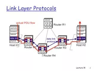
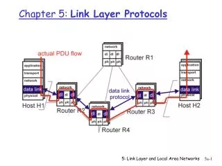
Common Protocols and Interfaces - Part 1 LLC and MAC Sublayer Protocols • Together with the physical layer, data link standards make up the core IEEE 802.X protocol standards. • Refer to Figure 7.18 (p. 254) • The MAC layer manages communications across the physical medium, defines frame assembling and disassembling, and performs error detection and addressing functions • The LLC layer interfaces with the network layer through Service Access Points (SAPs) • Refer to Figure 7.19 (p. 254) • Multiple MAC protocols can exist under the same LLC • Refer to Figure 7.20 (p. 255)
Common Protocols and Interfaces - Part 1 Logical Link Control (LLC) Sublayer • The LLC protocols are designed for peer-to-peer communications over multipoint bus and ring topologies. • The LLC allows a 802, .4, or .5 protocol to carry multiple, logical sub-network traffic of each protocol over the same physical medium, such as the LAN • Two major modes of service interfacing • Connection-oriented: • uses SAP peer-to-peer connection with flow control and error recovery • Connectionless • class 1: unacknowledged connectionless • class 2: acknowledged connectionless
Common Protocols and Interfaces - Part 1 Logical Link Control (LLC) Sublayer (Continue…) • Refer to Figure 7.21 (p. 265) • When the logical data link layer receives user data in the form of an information field, it adds a header to this field and forms what is called a Protocol Data Unit (PDU) • Refer to Figure 7.22 (p. 256) • The PDU header contains both a destination address and a source address of the origination port for a network hardware device or application for network software. • Both are referred to as Service Access Points (SAPs)
Common Protocols and Interfaces - Part 1 Media Access Control (MAC) Sublayer • The MAC sublayer manages and controls communications across the physical media, manages the frame assembling and disassembling, and performs error detection and addressing functions. • There is also one MAC layer bridge protocol 802.1d bridge (Spanning Tree) designed to interface any 802 LAN with any other 802 LAN. • When the MAC layer receives the LLC PDU, it adds a header and trailer for transmission across the MAC layer (and physical medium) • Refer to Figure 7.23 (p. 258)MAC addresses are unique and identify physical station points on the network
Common Protocols and Interfaces - Part 1 Media Access Control (MAC) Sublayer (Continue…) • The LLC header has been extended to allow more than 64 SAP values to be identified. • Also, two more field were added to the MAC frame format - an Organizationally Unique Identifier (OUI) for defining an organization that will assign a Protocol Identifier (PID) for the type of Ethernet • Refer to Figure 7.24 (p. 259)
Common Protocols and Interfaces - Part 1 802.3 CSMA/CD (Ethernet) • Uses Carrier Sense Multiple Access with Collision Detection (CSMA/CD) within a standard Ethernet frame, across a common physical medium bus with channel-attached MAC addressed stations • Theoretically it can send at rates reaching 10Mbps • Maximum size of 802.3 frame is 1500 bytes • CSMA/CD allows for stations to both transmit and receive data in a “best-effort” data delivery system-no guarantee of data delivery is made • During a collision the end stations initiate a “back-off” algorithm and follow a mathematical formula to randomize each station’s next attempt to retransmit. • The medium can be either basedband or broadband • Refer to Figure 7.25 (p. 260)
Common Protocols and Interfaces - Part 1 802.4 Token Bus • A logical ring is formed on the physical bus, and each station knows only the preceding station on the bus. • A token is passed down the bus, from station to station in logical ring sequence and by descending station address • Refer to Figure 7.26 (p. 261) • Refer to Figure 7.27 (p. 261)
Common Protocols and Interfaces - Part 1 802.3 Token Ring A token circulates around the physical “hub” and logical “ring” topology and provides “priority access” to the network medium. The token is either free or busy. At heavy load conditions, the Token Ring protocol is much more bandwidth efficient than other LAN protocols The maximum frame size for a Token frame using the 4 Mbps medium is 4,000 bytes and for the 16 Mbps medium is 17,800 bytes Refer to Figure 7.28 (p. 262) Refer to Figure 7.29 (p. 263)
Common Protocols and Interfaces - Part 1 Fiber Distributed Data Interface (FDDI) • It was designed to provide either a high-performance LAN or a campus backbone. • Shared FDDI MANs can be connected via DS3 or OC-3 SONET pipes to form a wider area network, subject to distance constraints. • FDDI operates over both physical- and MAC-layer protocols, providing a 100 Mbps transmission over a dual, counter-rotating optical fiber ring between nodes. • Up to 500 dual-attachment connection devices can interface to the FDDI ring in series. • FDDI ring supports a maximum of up to 1000 stations, with a maximum distance between stations of 2 km and a maximum ring total circumference of 100 to 200 km
Common Protocols and Interfaces - Part 1 Fiber Distributed Data Interface (FDDI) (Continue…) • FDDI operation is very similar to Token Ring protocol • FDDI defines a Physical Medium Dependent (PMD) layer for single or multimode operation through full-duplex connectors, optical tranceivers, and optional bypass switches. • The physical layer of FDDI consists of a class A dual attachment physical interface via the PMD sublayer. • Refer to Figure 7.30 (p. 264) • The information field (data packet) ranges from 128 to 4500 bytes whereas the maximum frame length is 9000 bytes • Refer to Figure 7.31 (p. 265)
Common Protocols and Interfaces - Part 1 Fiber Distributed Data Interface (FDDI) (Continue…) • Basic operation is similar to Token Ring with the exception that each idle station on the ring has a chance to seize a passing free token • Refer to Figure 7.32 (p. 266) • Two classes of stations use the FDDI ring • Class A : utilize both the inner and outer fiber rings. Also called Dual Attachment Stations (DAS) • Class B : cannot provide reroute, and use only the outer ring. They are Signle Attachment Stations (SASs) • Refer to Figure 7.33 (p. 267)
Common Protocols and Interfaces - Part 1 Fiber Distributed Data Interface (FDDI) (Continue…) • During a link failure all class A stations can automatically reconfigure to use the secondary ring. This capability is called self-healing • Class B stations will be offline because the primary ring they use is inactive during a failure condition. • Any station on the link can be taken down without affecting the FDDI ring. • Refer to Figure 7.34 (p. 267)
Common Protocols and Interfaces - Part 1 Fiber Distributed Data Interface (FDDI) (Continue…) • FDDI can be implemented with either single mode o rmultimode fiber-optic cable • FDDI can be transmitted over shielded and unshielded twisted-pair distances up to about 100 m. • WAN attachment is accomplished through both encapsulating and translating dual-attached bridges • Refer to Figure 7.35 (p. 268) • Refer to Advantages and Disadvantages of FDDI LAN on page 269
Common Protocols and Interfaces - Part 1 FDDI-II • The FDDI-II protocol structure will allow FDDI LANs to transport multiplexed asynchronous packet data and isochronous circuit-switched data • A hybrid multiplexer layer has been added between the physical and MAC sublayer and frames are now called cycles. • Multiple 6 Mbps portions of data can be dynamically allocated to DS1 channels to support voice, data, and video. • This 6 Mbps consists of multiple 64 kbps channels. Each cycle can carry up to 16 channels, and each channel up to 6.144 Mbps.
Common Protocols and Interfaces - Part 1 FDDI-II (Continue…) • This service is good for interconnection of PBX equipment to the LAN and WAN, and combines telecommunications and data communications mixed media on the same fiber. • To date, the deployment of FDDI-II has been stalled by the lack of a vendor to produce a chipset and the offering of low-speed LAN ATM interface cards • FDDI contains some distance limitations
Common Protocols and Interfaces - Part 1 100-Mbps Ethernet: 100BASET and 100VG-AnyLAN 100BASE-T Fast Ethernet • It speeds up the existing CSMA/CD media access control mechanism to 100 Mbps • 100BaseT is an IEEE 802.3 standard and offers three major segment types: • T4: uses four-pair twisted wiring • TX: uses two-pair twisted media • FX: uses two-strand fiber-optic cable
Common Protocols and Interfaces - Part 1 100VG-AnyLAN • It is called VG, Fast Ethernet, Fast Toekn Ring, and Demand Priority • The IEEE standard for 100VG-AnyLAN is 802.12, while 100BASEVG is 802.11 standard • 100VG-AnyLAN can operate over four-pair UTP (up to 100 m), two-pair STP (up to 200 m), and fiber-optic cable (up to 2000 m). • A deterministic demand priority scheme is used to create a predictable order by which nodes share the network. • 100BASET is best used as an upgrade to existing 10 Mbps Ethernet when cabling permits but continued interoperability is required
Cisco Configuration & IOS Management Commands
Objectives • Use the setup feature on a Cisco router • Log into a router in both user and privileged modes • Find commands by using the help facilities • Use command on a router by using the editing command • Set the router passwords, identification, and banners • Configure an interface with IP addresses and subnet masks • Copy the configuration to NVRAM
Cisco Router User Interface • Cisco Router IOS • Connecting to a Cisco Router • Bringing up a Router
Bringing up a Router • Boot-up process: #1: POST #2: Looks for the Cisco IOS from Flash memory #3: IOS loads & looks for a valid configuration; • startup-config • stored in nonvolatile RAM (NVRAM) #4: If a valid config is not found in NVRAM: • setup mode
Setup Mode • Basic Management Setup • Extended Setup • Command-Line Interface
Logging into the Router • User mode: • Router> • Used mostly to view statistics • Privileged mode: • Router# • Used to view & change router configuration