Drilling Bits
DRILLING ENGINEERING. Drilling Bits. Topics of Interest:. Various bit types available (classification). Criteria for the selection for the best bit for a given situation. Standard methods for evaluating dull bite. Factors affecting bit wear and drilling speed.

Drilling Bits
E N D
Presentation Transcript
DRILLING ENGINEERING Drilling Bits
Topics of Interest: • Various bit types available (classification). • Criteria for the selection for the best bit for a given situation. • Standard methods for evaluating dull bite. • Factors affecting bit wear and drilling speed. • Optimization of bit weight and rotary speed.
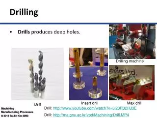
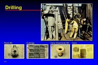
5.1 Types of Bits 1. Drag Bits: Consist of fixed cutter blades that are integral with the body of the bit and rotate as a unit with the drill string (19th century). 2. Rolling Cutter Bits: (1909) have two or more cones containing the cutting elements which rotate about the axis of the cone as the bit is rotated at the bottom of the hole.
5.1.1 Drag Bits • Design Features: • Number and shape of the cutting blades or stones. • Size and location of the water courses. • Metallurgy of the bit and cutting elements. • Drilling is achieved by physically blowing cuttings from the bottom of the bore-hole. Types (a) Steel cutter bits (b) Diamond bits (c) Polycrystalline diamond bits
Advantages • No rolling parts which require strong clean bearing surfaces • Because it is made from one solid piece of steel there is less chance of bit breakage, which would leave junk in the bottom of the hole. • Steel Cutter Bits:Best for soft, uniform unconsolidated formations. Now, replaced by other types in all area. • Diamond Bits:Best for hard non-brittle formations. • The face or crown of the bit consists of many diamonds set in a tungsten carbide matrix. • Fluid courses are provided in the matrix to direct the flow of drilling fluid over the face of the bit.
Shape of crown profit is important 1. Step type 2. Long taper (straight hole, high wt.) 3. Short taper (easier to clean) 4. Non taper (directional drilling) • Size and number of diamonds, depend on the hardness of the formation. • For hard formations: many small stones (0.07-0.125 carrot) • For soft formations: few large stones (0.75-2.0 carrot) • Pressure drop across the face of the bit Pump pressure measured with the bit off bottom-pump pressure with the bit drilling = 500 – 1000 psi • Manufacturer usually provide estimate of approximate circulating rate required establishing the needed pressure drop across the bit.
5.1.2 PolyCrystalline Diamond (PCD) Bits • Since the mid 1970’s a new family of drag bits has been made possible by the introduction of a sintered polycrystalline diamond drill blanks, as a bit cutter element. • The drill blanks consist of a layer of a synthetic polycrystalline diamond about 1/64 in. thick that is bonded to a cemented tungsten carbide substrate in a high-pressure high-temperature process. • It contains many small diamond crystals bonded together. • The PCD is bonded either to a tungsten carbide bit-body matrix or to a tungsten carbide stud that is mounted in a steel bit body.
They perform best in soft, firm, and medium-hard, non-abrasion formations that are not gummy. • Good results are obtained in carbonates or evaporates that are not broken up with hard shale stringers. Also good in a sandstone, siltstone, shale. • Design of crown profile is important, double-cone and flat profile. • Size, shape, number of cutters and angle of attack back rake, side rake and exposure: -20
5.1.3 ROLLING CUTTER BITS • The three-cone rolling cutter bit is by far the most common bit. • Available with a large variety of tooth design and bearing types. • Maximum use is made of limited space. • Cone offset to stop rotating periodically to scrape the hole like (PCD) bits. • It increases drilling speed but tooth wears faster. (4 for soft, 0 for hard) • Shape of teeth: long widely spaced steel teeth are used for drilling soft formations.
As the rock type gets harder the tooth length and cone offset must be reduced to prevent tooth breakage. • Tooth action = Scraping and twisting • Zero offset cones action = Crushing • Smaller tooth allows more room for the construction of stronger bearings
Classification of Tricone Bits (a) Milled tooth cutters (b) Tungsten carbide insert cutters • Hard facing on one side of the tooth allows self sharpening • Chipping tends to keep tooth sharp. • Intermeshing is advantageous. • Heel teeth = outer-raw very difficult job it wears it leads to out of gauge bit (hole).
Cheapest bearingassembly consist of: • Roller-type outer bearing • Ball-type intermediate bearing • Friction-type nose bearing All standard bearings are lubricated by drilling fluids. • Intermediate cost bearing assembly is the sealed bearing assembly-lubricated by grease. • Expensive assembly: Journal bearing must have effective grease seals. It gives long bearing life.
Example tungsten carbide insert cutter used in rolling cutter Bits
Mohr’s circle graphical analysis
5.3 Bit Selection and Evaluation • Determined by trial and error • Most valid criterion: drilling cost per unit interval drilled. (1.16) Initial selection is based on formation characteristics and drilling cost in an area. • Drillability: a measure of how easy the formation is to drill. • Abrasiveness:a measure of how rapidly the tooth of milled tooth bit will wear when drilling the formation. • Rules of Thumb: • Table 5.5: Bit types often used in various formation types.
5.3.1 Grading Tooth Wear • Tooth wear of milled tooth bits is graded in terms of fractional tooth height that has been worn away and is reported to the nearest eighth. • Example: Half original tooth height has been worn away, the bit will be graded as T4, i.e. the teeth are 4/8 worn. “BT”: Broken teeth in a remarks column. • The average wear of the row of teeth with the most severe wear is reported. • Measure the height before and after the bit run. • Rapid visual estimates with experience. • Tooth wear of Insert bits is reported as the fraction of the total number of inserts that have been broken or lost to the nearest eighth. • Example: Half the inserts broken or lost it would be graded T4. i.e. 4/8 of the inserts are broken or lost.
5.3.2 Grading Bear Wear • Difficult to evaluate in the field. • Must be disassembled. • Bearing failure results in; • Cones do not rotate “locked” • Extremely loose cones. • Code B8 : Bearings are 8/8 worn Bearing failure B7: Slightly loose cone If it cannot be detected: It is estimated from the number of hours left in the bearing.
B1 B4 B7 Estimated Hours Left Actual Rotating Hours
5.3.3 Grading Gauge Wear • When wear is in the base area of the rolling cones the bit will drill under sized hole. • A Ring Gauge and a Ruler are used to measure the amount of gauge wear. • Example:Bit loses 0.5 inch in diameter the bit is graded G-O-4 O = Out of gauge bit I = In gauge bit 4 = 4/8 of inch.
Common Abbreviation used in describing bit condition in dull bit evaluation.
5.6 Termination A Bit Run • There is always uncertainty about the best time to terminate a bot run and begin tripping operations. • Tooth and Bearing wear equations give at best a rough estimate of when the bit will be completely worn. • It is helpful to monitor the torque needed to rotate the bit. The torque increases or fluctuates when a cone become locked due to worn bearing. • If a sharp decrease in penetration rate is noticed it is advisable to pull the bit before it is completely worn. • If the lithology is uniform, the total drilling cost can be minimized by minimizing the cost of each bit run. • Keep a current estimate of cost/ft for the bit run, when it starts to increase pull the bit even if significant life remains.
5.7 Factor Affecting Penetration Rate • Bit type • Formation Characteristics • Drilling Fluid properties • Bit operation conditions (bit weight. and speed) • Bit tooth wear • Bit Hydraulics.
5.8.3 Selection of Bit Weight and Rotary Speed • The weight applied to the bit and the rotational speed of the drilling sting have a major effect on the both the penetration rate and the life of the bit. • Consideration must be given to the following items when selecting the bit weight and rotary speed. • The effect of the selected operating conditions on the cost per foot for the bit run question and on subsequent bit runs. • The effect of the selected operating conditions on crooked hole problems.
The max. desired penetration rate for the fluid circulating rate and mud processing rates available and for efficient kick detection. • Equipment limitations on the available bit weight and rotary size.
5.7.4 Operating Conditions • The bit weight and rotary speed have a tremendous effect on rate of penetration. • As shown in the fig, • No significant penetration rate is obtained until the threshold bit weight is applied (Point a). • Penetration rate then increases rapidly with increasing values of bit weight for moderate values of bit weight (Segment ab). • A linear curve is often observed at moderate bit weight, subsequent increase in bit weight causes only slight improvement in the penetration rate (segment cd) • In some cases, a decrease in penetration rate is observed at extremely high values of bit weight (Segment de). This behavior is called bit floundering. It is due to less efficient bottom hole cleaning at higher rates of cutting generation.
d Rotary Speed c e b a Weight on bit