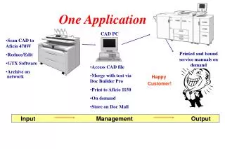
Carman scan ONE application
Carman scan ONE application. CONTENT. CRANK ANGLE SENSOR CAM POSITION SENSOR TPS AIR FLOW SENSOR OXYGEN SENSOR INJECTOR IGNITION ISC VALVE AIR TEMPERATURE SENSOR COOLANT TEMPERATURE SENSOR BATTERY VOLTAGE KNOCK SENSOR VEHICLE SPEED SENSOR EGR VALVE CANISTER PURGE VALVE


Carman scan ONE application
E N D
Presentation Transcript
CONTENT CRANK ANGLE SENSOR CAM POSITION SENSOR TPS AIR FLOW SENSOR OXYGEN SENSOR INJECTOR IGNITION ISC VALVE AIR TEMPERATURE SENSOR COOLANT TEMPERATURE SENSOR BATTERY VOLTAGE KNOCK SENSOR VEHICLE SPEED SENSOR EGR VALVE CANISTER PURGE VALVE OXYGEN SENSOR HEATER
CRANK ANGLE SENSOR-1 CHECK METHOD With connecting the Oscilloscope, Set the Sampling rate to over 250KHz and Compare the Counts and width of tooth between Long tooth after measuring the Crank Angle signal when Engine trouble is appearing. < Reference > This signal must be measured on over 250KHz sampling rate at least. In case of low memory capacity, Measuring time is very short. Thus It must be measured on time of appearing the Engine trouble as triggering the signal. But it is difficult to catch on time of Engine trouble. NOTICE : Ground line should be earth to engine or chassis to see the absolute signal.
CRANK ANGLE SENSOR-2 • 1. Find and connect the Signal and Ground line referencing the wiring diagram. • 2. After measuring the Signal, Compare the measured signal with Normal Signal. • 3. Check if Operating of Related components with this signal is Normal through checking the normal condition value of components • < Related components > • 1. Injector Timing and working status. • 2. Ignition timing and working status • 3. Synchronization with CAM angle signal
CRANK ANGLE SENSOR-3 WAVE ANALYSIS • WAVE ANALYSIS-MAGNETIC TYPE-1 • When the target wheel (The ring that has teeth) pass by the magnetic crankshaft sensor, electric pressure is generated during cutting the lines of magnetic force. The shorter the distance between crankshaft sensor and the target wheel (air gap) is and the higher the engine revolution is high electric pressure is generated. The longer and the slower, low electric pressure is generated.
CRANK ANGLE SENSOR-4 • WAVE ANALYSIS-MAGNETIC TYPE-2 • ECU can recognize tooth signal not by means of peak signal but by means of rising edge and falling edge. • That is, if the output voltage of the magnetic sensor is over about 20mV ECU determines ON, if about –5 ~ -10mV ECU determines OFF, and finally ECU recognize one ON/OFF cycle as one tooth.
CRANK ANGLE SENSOR-5 • WAVE ANALYSIS-MAGNETIC TYPE-3 • If noise is occurred and ECU recognizes this noise signal as real tooth signal, ECU cannot detect long tooth or detect more increased short tooth and it results in fuel cut and ignition cut. So when noise is exist, it must be checked abnormal injection.
CRANK ANGLE SENSOR-6 • WAVE ANALYSIS-MAGNETIC TYPE-4 • The level change (Edge: from high to low level/ from low to high level) of the camshaft signal must be occurred at least two short teeth before from the long tooth. • If the level change of the camshaft signal is occurred at long tooth or at short tooth before one tooth from the long tooth, We must check pulley (TDC) position and modify it.
CRANK ANGLE SENSOR-7 • WAVE ANALYSIS-HALL TYPE-1 • This one is hall type sensor and circuit is included within sensor and 12V power is supplied. If metal is passed the sensing part within 1.0±0.5mm gap, 5V (or 12V with another sensor) output voltage is generated through sensor internal circuit.
CRANK ANGLE SENSOR-8 • WAVE ANALYSIS-HALL TYPE-2 • ECU can recognize tooth signal not by means of peak signal but by means of rising edge and falling edge. • That is, if the output voltage of the magnetic sensor is over about 200mV ~ 2.5V ECU determines ON, if about 100mV ~ 1.5V ECU determines OFF, and finally ECU recognize one ON/OFF cycle as one tooth.
CRANK ANGLE SENSOR-9 • WAVE ANALYSIS-HALL TYPE-3 • If noise is occurred and ECU recognizes this noise signal as real tooth signal, ECU cannot detect long tooth or detect more increased short tooth and it results in fuel cut and ignition cut. So when noise is exist, it must be checked abnormal injection. < When ignition wave is occurred during crank angle signal ON >
CRANK ANGLE SENSOR-10 < When ignition wave is occurred during crank angle signal OFF > < When ignition wave is occurred at the beginning of crank angle signal ON (or OFF) > WAVE ANALYSIS-HALL TYPE-4
CRANK ANGLE SENSOR-11 • WAVE ANALYSIS-HALL TYPE-5 • The level change (Edge: from high to low level/ from low to high level) of the camshaft signal must be occurred at least two short teeth before from the long tooth. • If the level change of the camshaft signal is occurred at long tooth or at short tooth before one tooth from the long tooth, We must check pulley (TDC) position and modify it.
CRANK ANGLE SENSOR-12 • WAVE ANALYSIS-OPTICAL TYPE-1 • This is an optical sensor. During round plate (It is called target wheel) that has holes is revolved with camshaft, the light is shone. If the light passes through the hole, out put voltage is generated. This sensor uses this principle and need power to be operated.
CRANK ANGLE SENSOR-13 • WAVE ANALYSIS-OPTICAL TYPE-2 • ECU can recognize tooth signal not by means of peak signal but by means of rising edge and falling edge. • That is, if the output voltage of the magnetic sensor is over about 200mV ~ 2.5V ECU determines ON, if about 100mV ~ 1.5V ECU determines OFF, and finally ECU recognize one ON/OFF cycle as one tooth.
CRANK ANGLE SENSOR-14 • WAVE ANALYSIS-OPTICAL TYPE-3 • If noise is occurred and ECU recognizes this noise signal as real tooth signal, ECU cannot detect long tooth or detect more increased short tooth and it results in fuel cut and ignition cut. So when noise is exist, it must be checked abnormal injection.
CRANK ANGLE SENSOR-15 • WAVE ANALYSIS-OPTICAL TYPE-4 • The level change (Edge: from high to low level/ from low to high level) of the camshaft signal must be occurred at least two short teeth before from the long tooth. • If the level change of the camshaft signal is occurred at long tooth or at short tooth before one tooth from the long tooth, We must check pulley (TDC) position and modify it.
CRANK ANGLE SENSOR-16 FIELD EXAMPLE < Example 1 > Vehicle : New Sephia 1.5L SOHC, Odometer : 7,200Km Problem description : Engine is started with hesitating. Engine is stopped soon after starting in cold ambient condition and restart is hard. Cause : Power, which is supplied, to distributor is cut during very short time when key is released after engine start. This phenomenon cause abnormal crank angle signal and it result in engine problem. Signal measurement
CRANK ANGLE SENSOR-17 • Explanation : When key is released after engine start, ECU doesn’t inject fuel due to missing crank angle signal by the bouncing phenomenon(Repeat contact and non-contact) • Enlargement of application: The change of sudden engine speed is due to injection fuel cut or abnormal ignition timing control. Most of this phenomenon is case that ECU doesn’t acquire normal crank angle signal, so crank angle sensor signal should be checked whether it is normal or not. And ignition timing and fuel injection control should be checked at the same time. • A.In case of back-fire occurrence of LPG vehicle • B.In case that engine stall is suddenly occurred in idle sate • C.In case that engine vibration is intermittently occurred • D. In case that engine is started with hesitating as jamming flywheel in self motor
CRANK ANGLE SENSOR-18 • < Example 2 > • Vehicle : Sephia 2 1.5L SOHC, Odometer : 24,000Km / Credos 2.0L DOHC LPG • Problem description : • - Gasoline vehicle : Engine is started after hesitating during 0.5[sec] as jamming flywheel in self-motor or engine is not started with the phenomenon. • - LPG vehicle : Backfire is happened when engine start. • Cause : Injector opening phase is abnormal and ignition timing is controlled with intake stroke. Signal measurement
CRANK ANGLE SENSOR-19 • Explanation : When flywheel is jammed in self-motor with initial engine cranking, vibration is occurred. ECU regard it as tooth signal and then first normal crank signal is acquired as long tooth. It results in wrong TDC calculation in ECU and abnormal fuel injection time and ignition timing control. • Enlargement of application : It is example that is occurred by wrong acquisition of ECU. Even though signal is normal, in case that ECU acquires it as abnormal signal, trouble may be detected. Therefore if injection time and ignition timing control is out of normal range, crank angle signal should be. • A. In case of back-fire occurrence of LPG vehicle • B. In case that engine stall is suddenly occurred in idle sate • C. In case that engine vibration is intermittently occurred • D. In case that engine is started with hesitating as jamming flywheel in self motor
CRANK ANGLE SENSOR-20 • < Example 3 > • Vehicle : Avella / Sephia 1.5L SOHC/DOHC , Odometer : 24,000Km / Credos 1.8L/2.0L DOHC LPG Taxi (Optical distributor equipped) • Problem description : Engine stall is occurred at times and once the problem is happened it is repeated many times. And after maintaining normal state for long time, engine stall is suddenly occurred. And then engine is not started. • Cause : Crank angle signal is occasionally missed or noise is occurred. Signal measurement
CRANK ANGLE SENSOR-21 • Explanation : In case of missing crank angle signal and noise occurrence, ECU recognize wrong tooth number. At this time injection and ignition is cut until tooth number is identified. If tooth number is corrected during injection and ignition cut, it is started again but engine stall may be occurred before ECU recognize it. • Enlargement of application : In case of sudden engine stall without abnormal engine operation, it is due to mainly abnormal crank angle signal. In this case, crank angle signal, injection time and ignition timing should be checked together and if missing injection or ignition is found out, check noise occurrence after amplifying crank angle signal. • A. In case of back-fire of LPG vehicle • B. In case that engine stall is suddenly occurred in idle sate • C. In case that engine vibration is intermittently occurred • D. In case that engine is started with hesitating as jamming flywheel in self motor
CAM POSITION SENSOR-1 CHECK METHOD • With connecting the Oscilloscope, Set the Sampling rate to over 250KHz and Compare the Counts and width of tooth between Long tooth after measuring the Cam Angle signal when Engine trouble is appearing. • < Reference > This signal must be measured on over 250KHz sampling rate at least to see the effect for noise. In case of low memory capacity, Measuring time is very short. Thus It must be measured on time of appearing the Engine trouble as triggering the signal. But it is difficult to catch on time of Engine trouble NOTICE : To measure the signal, ground line should be earth to chassis or engine.
CAM POSITION SENSOR-2 • 1. Find and connect the Signal and Ground line referencing the wiring diagram. • 2. After measuring the Signal, Compare the measured signal with Normal Signal. (1) Find the Rising point and Falling point of Cam signal through the tooth counts of crank angle signal. (2) Calculate the high and low level of cam signal as the crank angle sensor signal’s tooth counts. • 3. Check if Operating of Related components with this signal are Normal through checking with the normal condition value of components. < Related components > 1. Injector Timing and working status. 2.Ignition timing and working status
CAM POSITION SENSOR-3 WAVE ANALYSIS • Magnetic type • Sensor signal voltage is as following graph.
CAM POSITION SENSOR-4 < Reference > The high and low phase change of Cam signal must be generated before long tooth of the crank signal that is at least 3 short teeth before.
CAM POSITION SENSOR-5 • WAVE ANALYSIS-Optical type This is an optical sensor. During round plate (It is called target wheel) that has holes is revolved with camshaft, the light is shone. If the light passes through the hole, out put voltage is generated. This sensor uses this principle and need power to be operated.
CAM POSITION SENSOR-6 • The level change (Edge: from high to low level/ from low to high level) of the camshaft signal must be occurred at least two short teeth before from the long tooth. • If the level change of the camshaft signal is occurred at long tooth or at short tooth before one tooth from the long tooth, We must check pulley (TDC) position and modify to make cam signal level change at least 2 short teeth before from the long tooth.
CAM POSITION SENSOR-7 • WAVE ANALYSIS-Hall type • This one is hall type sensor and circuit is included within sensor and 12V power is supplied. If metal is passed the sensing part within 1.0±0.5mm gap, 5V (someone is 12V) output voltage is generated through sensor internal circuit.
CAM POSITION SENSOR-8 • The level change (Edge: from high to low level/ from low to high level) of the camshaft signal must be occurred at least two short teeth before from the long tooth. • If the level change of the camshaft signal is occurred at long tooth or at short tooth before one tooth from the long tooth, We must check pulley (TDC) position and modify to make cam signal level change at least 2 short teeth before from the long tooth.
CAM POSITION SENSOR-9 FIELD EXAMPLE • Vehicle : Avante 1.5L DOHC, Odometer : 48,000Km • Problem description : When acceleration during driving, the performance is lack. And trouble code of camshaft angle sensor is detected at times. • Cause : The trouble of camshaft angle sensor is due to no change of polarity between two validated long tooth. The acceleration performance is lack because camshaft sensor is assembled with 6[CRK] retard. Signal measurement
CAM POSITION SENSOR-10 • Explanation : In case that ignition timing is controlled by ECU, crankshaft and camshaft signal should exactly synchronized. Check the problem after comparing with normal crankshaft and camshaft signal. • Enlargement of application : If camshaft edge is close to long tooth detection point, it means that ignition timing is retarded. So, performance is decreased. If it is opposite case, it means that ignition is advanced and it results in knocking, lack of performance and engine damage.
TPS-1 CHECK METHOD • 1. Check the Signal voltage with connecting the Oscilloscope. • 2. After connecting the Hi-scan, Check that HI-scan detected the Idling state without stepping on the accelerator pedal. • <Connecting Method> • To measuring the Noise and Resistance throughout TPS wiring line exactly, That must be measured on not Connector side but closest position to ECU (within 30mm). - TPS Signal line, TPS Ground line NOTICE : To measure the signal, ground line should be earth to chassis or engine
TPS-2 1. Find and connect the Signal and Ground line referencing the wiring diagram. 2. After measuring the signal, compare the measured signal with Normal signal. (1) After checking in IDLE state, Measuring the signal at WOT (Whole Open Throttle) as stepping on the accelerator pedal. (2) It prefers to check the Air mass flow signal in the same time if possible. < Checking item > (1) Check that IDLE state is well recognized through the Scanner. (2) Check that TPS signal value changed exactly according to Throttle variation. (3) Check that TPS adaptation value is learnt well in IDLE state.
TPS-3 WAVE ANALYSIS • Check the output voltage according to the pedal opening degree. < Spec. : Specification which used during development period >
TPS-4 • < Measurement : Measure the mass air flow and TPS during full acceleration from idle> • ECU recognized TPS signal check is essential. Through the scanner, TPS value vs. TPS adapted value check is required during idle. If TPS value is bigger (around 1.2) than adapted value, engine idle can be unstable due to ECU not recognized idle status.
TPS-5 FIELD EXAMPLE • < Example 1 >The problem by noise • Vehicle : Matiz, Odometer : 4,800Km • Problem description : RPM cycling is sometimes taken place in idle state with engine vibration. And a lot of CO emission(1.7%) comes from exhaust gas in idle state. • Cause : RPM cycling is taken place because ECU doesn’t recognize idle state by noise detection of TPS signal. Whenever noise is detected, ECU recognizes it as working rapidly acceleration pedal. And it is cause of rich injection control as adding fuel correction when acceleration < Rich injection control by fuel correction when acceleration > < Amplification of noise signal : ECU doesn’t recognize idle state >
TPS-6 • Explanation : The noise is not occurred after separating TPS signal line from TCU connecting. But if it is TPS signal line which must be used with TCU connecting, noise may be reduced as separating TCU from connecting part as far as possible. • Enlargement of application : If noise is occurred in TPS signal, find what is connected with TPS signal and ground line. And check noise after separating it. If noise is reduced, remove connecting part. But if removal is impossible, find point that the lowest noise is detected as moving connecting part. Nevertheless, if noise is not decreased, find point that the lowest noise is detected as moving ground line and connect it. It may be implemented by shield line.
TPS-7 • < Example 2 > Micro cut-off occurrence • Vehicle : Accent 1.3 & 1.5L SOHC (Siemens system), Odometer : Don’t care • Problem description : Sometimes engine is rough idle state. The floating is occurred without idle recovery and surging is taken place when acceleration. TPS value that is measured from scanner is normal but TPS value is very small in idle state. • NOTICE : Absolutely TPS value in idle state >>> Adapted TPS value in idle state • Cause : TPS signal is cut for very short time( 40 –120usec ). ECU regard it as TPS value (Below 0.05volt) that is measured with micro cut-off phenomenon in idle state(If the idle TPS value which is memorized in ECU is less than normal one, it is set to idle TPS value). After that if it is again returned normal, ECU recognize it as working acceleration pedal and also don’t apply idle correction.
TPS-8 • Explanation : Finally, ECU doesn’t detect idle in spite of real idle state. So, it led to rough idle. The current vehicle (Production after Jun.1996 model year) have no problem with micro cut-off (Duration is less than 0.8) because ECU change TPS value after elapsed 0.8 [sec] in case that current TPS value is less than memorized one. • Enlargement of application : If engine is rough idle, first compare “absolutely TPS value” with “TPS adaptation value” from scanner in idle state. If these two values have difference more than 1.2 [TPS], ECU doesn’t detect idle in spite of real idle state. So, you must find root cause after inspecting why this phenomenon is happened. • Example : Micro cut-off / Bad return of acceleration cable / Bad connection of ground line. Signal measurement
TPS-9 • < Example 3 > The bad connection of TPS ground line • Vehicle : Rio 1.5L DOHC, Odometer : 3,200Km • Problem description : Sometimes engine is rough idle state. The floating is occurred without idle recovery and severe RPM cycling is taken place with electric load or A/C ON. • Cause : If engine becomes so hot, TPS signal is unstable in idle state by bad connection around fuse box. So, ECU doesn’t recognize idle state because the unstable signal is higher than “TPS adaptation value in idle”. It results in rough idle. Signal measurement
TPS-10 • Explanation : If RPM is unstable, the system which recognize idle by TPS signal(Without idle switch type) should check whether ECU recognize idle or not. • Enlargement of application : If engine is rough idle, first compare “absolutely TPS value” with “TPS adaptation value” from scanner in idle state. If these two values have difference more than 1.2 [TPS], ECU doesn’t detect idle in spite of real idle state. So, you must find root cause after inspecting why this phenomenon is happened. • Example : Micro cut-off / Bad return of acceleration cable / bad connection of TPS ground line.
AIR FLOW SENSOR-1 CHECK METHOD 1. With connecting the oscilloscope. 2. Check what the signal voltage is as stepping on and off the accelerator pedal in idle state. NOTICE : To measure the signal, ground line should be earth to chassis or engine.
AIR FLOW SENSOR-2 1. Find and connect the Signal and Ground line referencing the wiring diagram. 2. After measuring the signal, compare the measured signal with Normal signal. (1) After checking in IDLE state, Measuring the signal at WOT (Whole Open Throttle) as stepping on the accelerator pedal (2) It prefers to check the TPS (Throttle Position Sensor) in the same time if possible. 3. Check the followings with connecting the scanner after making the engine fully warmed-up and keeping Idling above 10 minutes. < Checking items> (1) Check that the additive adaptation value (fuel adaptation in IDLE) is in normal range (within ±0.8 msec). (2) Check whether the mass air flow value is changed as stepping on the accelerator pedal. (3) Check that the multiplicative adaptation is in normal range (within ±15%) after driving (over 3 days)
AIR FLOW SENSOR-3 WAVE ANALYSIS • MAP sensor • The output voltage of MAP sensor according to the pressure of surge tank is as follows.
AIR FLOW SENSOR-4 • Hot film / Hot wire type mass air flow sensor • The output voltage of MAF sensor according to the mass air flow(Kg/Hr) is as follows.
AIR FLOW SENSOR-5 • Karman vortex type • The output pulse is different from mass air flow.
AIR FLOW SENSOR-6 FIELD EXAMPLE • < Example 1 > In case of misfire occurrence from engine • Vehicle : MAP sensor equipped vehicle(SOHC engine is more severe => Misfire is often occurred with a little bit lean fuel control) • Problem description : The unstable RPM cycling(recovery after fast drop of RPM) and engine vibration are occurred in idle state. At the moment MAP sensor signal show spike phenomenon (Fast jump and drop of MAP sensor signal). • Cause : Misfire was occurred inside combustion chamber due to instantaneous lean fuel control(SOHC is over A/F 15.3 and DOHC is over A/F 15.7) with lean fuel correction(ECU decrease injection time because O2 sensor voltage is over 0.5 [volt]) of O2 sensor feedback Signal measurement
AIR FLOW SENSOR-7 • Explanation : If misfire is occurred from engine, piston speed is rapidly reduced. At the moment the mass air flow is rapidly decreased from surge tank and pressure inside surge tank is rapidly increased. So, MAP sensor signal is increased as jumping. • Enlargement of application : The pressure variation inside surge tank is related to piston speed. Without fuel supply, pressure inside surge tank is inverse proportion to piston speed. Indeed, if piston speed is fast pressure is low, if it is slow pressure is high. So, you can guess compression ratio through the fact. • If pressure inside surge tank is high when dry cranking(Cranking without fuel supply), piston speed is low and also it mean that compression ratio is high. In the contrary, if pressure inside surge tank is low, piston speed is high and also it mean that compression ration is low. Therefore The compression ratio can be relatively compared by surge tank pressure from dry cranking.