Download

1 / 50
670 likes | 1.29k Vues
Chapter 4 Flight Instruments. Avionics and Aircraft Systems. Flight Instruments. Why do we need flight instruments?. In the early days of flying there were no flight instruments. But there were plenty of crashes. By having flight instruments pilots can stay within safe

E N D
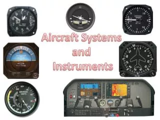
Chapter 4 Flight Instruments • Avionics and Aircraft Systems
Flight Instruments Why do we need flight instruments? In the early days of flying there were no flight instruments. But there were plenty of crashes. By having flight instruments pilots can stay within safe parameters and so reduce crashes.
Flight Instruments But even with basic flight instruments there were still crashes.
Flight Instruments Basics All aircraft have a basic layout for the primary instruments. Airspeed Indicator Artificial Horizon Altimeter This is known as The basic ‘T’ layout. Compass As aircraft progressed various other instruments were added but the basic ‘T’ is still used today.
Flight Instruments Basic ‘T’ Airspeed Indicator Artificial Horizon Altimeter Compass
Flight Instruments Artificial Horizon This instrument gives a representation of the visual horizon in relation to the position it was run up to speed in. It must always be run up to speed with the aircraft stationary to ensure it erects to the correct datum position. It is a gyro unit that holds it’s position in space no matter what attitude the unit is placed in. Blue is used to represent the sky and either black or brown to represent the ground.
Horizon Director Indicator – HDI Or Attitude Director Indicator - ADI Flight Instruments Moving Blind Full Roll +/- 85o Pitch Roll Command Bar - Parked Pitch Command Bar - Parked Flight Director Failure Flag Attitude Failure Flag Bank Angle Pointer Fixed Aircraft Symbol
Flight Instruments HDI - Erect, FD Off The Flight Director can be coupled to a navigation system or navigation aid i.e. ILS, TACAN or VOR.
Flight Instruments HDI - Erect, FD in use
Flight Instruments Compass Indicator This is the main instrument which indicates the compass heading and can display navigational information as well. It can get it’s compass heading information from various sources: Gyro Magnetic Compass INS (Inertial Navigation System) GPS (Global Positioning System) In modern aircraft the information can be displayed in either TRUE or MAGNETIC Heading.
000 Flight Instruments Horizontal Situation Indicator - HSI Compass Card Fixed Lubber N Miles Range Counter Course Counter NAV Warning Flag Course Pointer 335 Course Deviation Bar N MILES COURSE GS Warning Flag GS NAV Heading Index Course Pointer Tail Glideslope Deviation Bar DG Flag Compass Warning Flag D.G. Course Selector Knob Heading Selector Knob VOR To - From
Flight Instruments The International Standard Atmosphere (ISA) This is a model of the atmosphere which has been agreed internationally and is based on certain parameters. Temperature: + 15ºC at sea level. Air Pressure: 1013.25 Hectopascal (hPa) The hectopascal is the SI measurement of pressure and is equivalent to pounds per square inch (psi). 1013.25 hPa = 14.69595 psi.
Flight Instruments The temperature and pressure changes with increase in altitude. Temperature decreases and then increases. Pressure decreases and then stays constant. The table below shows the change.
Flight Instruments Pitot / Static Systems Flight instruments require the pressure of the air outside the aircraft and the pressure caused by the movement of the aircraft through the air. The pressure outside the aircraft is known as STATIC pressure. This pressure is measured by sampling the air from vents mounted parallel with the airflow Vent The pressure caused by the movement of the aircraft is known as PITOT pressure Airflow This pressure is measured by placing an open tube in the airflow to gather the air. Airflow
Flight Instruments Pitot / Static Systems There are various ways of gaining these pressures. On small aircraft a combined pitot probe and static vent is used. Pitot Static On large aircraft separate pitot tubes and static vents are used and a duplicate system can also be installed to cope with malfunctions.
Single Probes Static Vents Flight Instruments Pitot Static System - Probes & Static Vents The static vents are connected across the fuselage to give a balanced static pressure, making it more accurate.
Flight Instruments Pitot / Static Systems These pressures are fed directly to the flight instruments and used to display various information dependant on the instrument. On modern aircraft the pressures are fed to an AIR DATA COMPUTER which converts the pressure into digital signals and then feeds the digital data to electronic instruments. i.e. airspeed, altitude, Mach and true air speed. Because the pitot probe sits in the airflow it is susceptible to icing and is therefore heated electrically to stop ice forming.
Flight Instruments Airspeed Indicator- ASI This instrument indicates the airspeed of the aircraft and can have various layouts due to the range of speeds that different aircraft fly at. Typhoon Mach 2 or light aircraft 160kts. Maximum speed that can be indicated 200kts.
Flight Instruments Airspeed Indicator-ASI Mechanical stop at 40kts as the instrument is very inaccurate below this speed. The large pointer indicates in 10 kt increments and the small pointer indicates 100kt increments.
A simplified ASI Flight Instruments Airspeed Indicator-ASI To achieve an indication the instrument measures the atmospheric air pressure (Static) and the pressure caused by the aircraft moving through the air (Dynamic) which will include static air pressure. • The ASI measures the dynamic air pressure A pitot tube is a pipe with a hole in it’s end which is in the airflow and samples the airflow.
A simplified ASI Flight Instruments Airspeed Indicator-ASI • In forward flight the pressure above the diaphragm will consist of Dynamic + Static. Below, the pressure is just Static The two static pressures cancel out and the diaphragm will move due to the dynamic pressure
Mach Meter Flight Instruments Once the airspeed increases to approximately 300 kts it is harder to get accurate readings, therefore another method is used. The airspeed is displayed in relation to the speed of sound. Mach 1 = Speed Of Sound. Most modern airliners fly at 0.8 to 0.85 Mach. Initial Issue
Flight Instruments Altimeter This instrument is used to indicate the height of the aircraft above ground level or above a standard datum. The instrument measures static pressure which surrounds a sealed capsule. The capsule expands or contracts with pressure change which is measured and displayed on the instrument. The pressure in the capsule can be adjusted to give an indication relative to various datums. This adjustment is known as the pressure setting. The pressure setting can be expressed in Inches of Mercury (29.92) or Millibars (1013) is the standard atmosphere.
Flight Instruments Altimeter Pressure Settings QFE – The air pressure at the threshold of the runway - When set on an altimeter it gives the height of the aircraft in relation to the threshold. • QNH – The average air pressure at ground level for a • given area. • When set on an altimeter it gives the height of the • aircraft in relation to the average ground height in the area. • ISA Standard – The accepted international air pressure • at sea level. • When set on an altimeter it gives the height of the aircraft • to a standard, so all aircraft are operating at the correct • altitude.
Flight Instruments Altimeter The altimeter layout will vary depending on the maximum altitude the aircraft can achieve. Pressure Setting Pressure Setting Adjuster
0 10 0 FEET 1 9 2 8 35250 1013 29 92 3 . 7 HP IN.HG 6 4 5 Air Data Unit Flight Instruments Altimeter Modern aircraft now have electronic indicators which can display more information and are more accurate. This allows ATC to have the aircraft at a lower height separation and increase the density of the air traffic. Pitot Static
Flight Instruments Vertical Speed Indicator This instrument indicates the rate of climb or descent of the aircraft. It measures the rate of change of the static pressure. V.S.I.
1 2 RNG 10 RNG 10 1 1 2 2 4 .5 UP +05 4 4 .5 .5 +13 +05 +05 +13 -05 -05 0 6 +02 +02 +02 0 0 6 6 DN 4 .5 4 4 .5 .5 1 2 1 1 2 2 BRT BRT Flight Instruments Vertical Speed Indicator On modern aircraft the VSI has been combined with the Traffic Advisory System and both display on the same instrument electronically. 2 1 RNG 10 4 UP .5 Traffic Advisory is overlayed on the basic VSI. 0 6 DN 4 .5 2 1
Flight Instruments Turn And Slip Indicator Turn The turn needle indicates the rate of turn of the aircraft. Each division left or right of centre Indicates a rate 1,2 or 3 turn. Rate 1 = 180º/Min Rate 2 = 360º/Min Rate 3 = 540º/Min Slip The slip ball indicates if any yaw is being felt on the aircraft and in a balanced turn the ball should stay central.
NO TRACK LOW LOW FEET Flight Instruments Radar Altimeter This instrument indicates the height above the ground directly beneath the aircraft using radar signals. It is relatively accurate from 1000ft to 5000ft, but is very accurate below 1000ft. Used for low level flying to warn the crew if the aircraft descends below the minimum level allowed. Also on approach to land to warn the crew the aircraft is approaching the decision height. OFF A low warning brings on a light and gives an audio warning. SET PUSH TO TEST
Flight Instruments Pilot Instrument Panel ASI HDI/ADI Altimeter Mach Meter VSI Turn & Slip HSI
Flight Instruments The Glass Cockpit Many modern aircraft now have flat screen displays instead of individual instruments. The number of displays varies with aircraft type, but all have the facility to display the information that used to be displayed on individual instruments. The type of information can usually be transferred from one display to another, which covers failure of a display unit. The pilot can select what is to be displayed on each screen and if a system requires investigation , the system can be displayed on a screen. Checklists can also be displayed.
Flight Instruments The Glass Cockpit Airbus developed a system called EFIS, while Boeing developed EICAS. Both are very similar. EFIS
Flight Instruments EFIS
Flight Instruments EICAS
Flight Instruments EICAS