Download
1 / 28
350 likes | 642 Vues
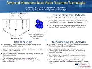
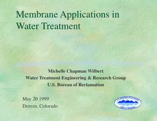
MEMBRANE TECHNOLOG Y FOR WATER TREATMENT. D. JAGAN MOHAN. New Technology Research Centre. University of West Bohemia. Plzen, Czech Republic. Fresh Water Need. Membranes for Water Treatment. Suspended solids. Dissolved salts. Colloids. Viruses. Bacteria. Parasites.

E N D
MEMBRANE TECHNOLOGY FOR WATER TREATMENT D. JAGAN MOHAN New Technology Research Centre University of West Bohemia Plzen, Czech Republic
Membranes for Water Treatment Suspended solids Dissolved salts Colloids Viruses Bacteria Parasites Org. macro. molecules 100mm 0.0001 0.001 0.01 0.1 1 10 polio virus smallest micro-organism Crypto- sporidium hair Reverse Osmosis Ultrafiltration Sand filtration Nanofiltration Microfiltration
Membrane Separations Symmetric. A cross section shows a uniform porous structure. Asymmetric. In a cross section, one can see two different structures, a thin dense layer and below a porous support layer. • Integral: the layers are continuous. • Composites: the active layer (thickness 0.1-1 μm) is supported over a highly porous layer (50-150 μm), sometimes both layers are of different materials.
Symmetric Membranes The cross section shows a uniformand regular structure Cross section Surface Symmetric ceramic membrane (Al2O3)
Thin Film Polyamide Membrane Polyester Fabric Polysulfone support PA membrane surface
Pore Geometry top layer thickness (0.1-1m) sub layer thickness (50-150 m) commercial interest The flux is inversely proportional to the thickness.
PA Layer PA Layer PS Support PS Support
Feed Water Cross-Flow Flux Semipermeable Membrane (~0.2 micrometers) Porous Interior (~0.5 mm thick) Permeate Asymmetric CA Membrane
Organic Phase (Heptane, etc.) + Acid Chloride COCl Cross-Link or Extension COCl COCl Cross-Link or Extension Diffusion NH2 NH2 COCl O NH2 Random Structure Cross-Link or Extension N C + HCl H COCl + Di-Functional Amine Aqueous Phase Reaction
Amide link Functional groups in the active layer Pressurized feed Polyamide (~100 nm) NH2 NHCO CONH NHCO Amine group CONH COOH Carboxylic group
Selective barrier (polyamide) Support Layer (Polysulfone) ~150 nm Reverse osmosis (RO)
Catalyst(s) (Pd, PEIs, etc.) CH3 N-N = O CH3 PA Layer Porous PS Polyester Support Pure water Catalytic Membrane Materials...
Charged membranes Ca++ Cl- SO4-- Na+ SO4-- Na+ Cl- Ca++ + + + + + - - - - - - + + + + + - - - - - - + Positively charged membrane Negatively charged membrane Negatively charged groups like SO3H+, COOH groups contribute to the negative charge of the membranes Quaternary ammonium groups like -N+ (CH3)4 Cl- contribute to the fixed positive charge of the membrane
Membrane Separations Cf Retinate (Concentrate) Feed Membrane Cp Simple scheme of a membrane module Permeate (Filtrate) Rejection :
Crossflow Mode Recirculation Concentrate Feed Membrane Pump Filtrate
Dead End Mode Feed Membrane Pump Filtrate
Materials Used Ceramic membranes Synthetic polymeric membranes PTFE, teflon PVDF PP PE Hydrophobic Alumina, Al2O3 Zirconia, ZrO2 Titania, TiO2 Silicium Carbide, SiC Hydrophilic Cellulose esters PSF/PES PI/PEI PA PEEK
1. Bio-organic Fouling Molecular Adsorption De-lamination PA PS The Issues... • Flux loss • Solute passage 2. Physico-Chemical Integrity
Membrane Fouling • Membrane fouling is referred to as the deposition or adsorption of the particles • contained in the feed stream on the membrane surface or in the membrane pores • This gel layer forms a secondary barrier to flow through the membrane ↓ flux ↓ membrane life ↑ energy use Schematics of membrane fouling mechanisms: (A) pore blockage, (B) pore constriction, (C) intermediate blockage and (D) cake filtration. • Membrane fouling has a negative impact on filtration performance as it decreases the permeate flux
Membrane Fouling • Physical/chemical/biological plugging of membranes by inorganic salts, dissolved organic matters, colloids, bacteria, etc. • Affects permeate water quality • Increases operational burden and cost • Reduces permeate water flux • Reduces feed water recovery • Damages membranes
Cleaning in Backwashmode Membrane Cleaning chemicals (if needed) Filtrate Tank
Cleaning in Forward Flushmode Concentrate Feed Membrane Pump
Characterization of membrane • Structure-relatedparameters (poresize, poresizedistribution, top layerthickness, surfaceporosity) • Permeation-relatedparameters (actual separationparametersusingsolutesthat are more or lessretainedbythemembranes - ‘cut-off’ measurements*) • Instruments : SEM, TEM, GPC, DMA, bubblepointmethod, porosimetry, AFM, IR (structuraldetermination) etc. * ‘cut-off’ is defined as the molecular weight which is 90% rejected by the membrane
Some Industrial Applications • Waste-water treatment • Clarification of fruit juice, wine and beer • Ultrapure water in the semiconductor industry • Metal recovery as colloidal oxides or hydroxides • Cold sterilization of beverages and pharmaceuticals • Medical applications: transfusion filter set, purification of surgical water • Continuous fermentation • Purification of condensed water at nuclear plants • Separation of oil-water emulsions