Download
1 / 38
380 likes | 415 Vues
Utilizing ZEMAX software, this paper explores designing progressive addition lenses (PALs) to enhance vision comfort and reduce distortion. Principles of aberration, distortion, and eyeball curvature are considered for optimal lens design. The study aims to improve the visual experience by adjusting lens parameters and areas for far, middle, and near distances.

E N D
Design of the progressive addition lens by the optical software ZEMAX
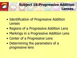
Outline • Absract • Introduction (a) Paper survey (b) Motivation • Principle and Specification • Design result • Conclusion & Future work • References
Outline • Absract • Introduction (a) Paper survey (b) Motivation • Principle and Specification • Design result • Conclusion & Future work • References
Abstract • Use the geometrical optics and the optical design software ZEMAX to design the progressive addition lens. • The progressive addition lens (PALs) are conformed with far、middle and near distance. • Obtain the PALs surface’s addition diopter map by using the multi-configuration to set far、middle and near distance. • The unit of the human’ eye is diopter (D).
Outline • Absract • Introduction (a) Paper survey (b) Motivation • Principle and Specification • Design result • Conclusion & Future work • References
Introduction(a) paper survey • The earliest progressive lens patent was submitted in 1907 by Owen Aves[1]. • Several early progressive lens design realised on a single surface, empolyed a class of surfaces similar in optical effect to the surface geometry of a curled elephant’s trunk, as shown in Fig.1.
Fig.1 Similar in principle to an elephant-trunk-shaped surface.[1]
Far area distortion distortion Near area • According to the view field, the progressive addition lens can divided to far、middle、near and distortion area[1,3], as shown in Fig. 2. Fig.2 The area distribution of the progressive addition lens.
Outline • Absract • Introduction (a) Paper survey (b) Motivation • Principle and Specification • Design result • Conclusion & Future work • References
Introduction(b) Motivation • If the PALs ADD become bigger, the middle and near area will become narrow. • Also the distortion area will compress into the middle area, and the distortion level will bigger. • Improve the distortion level to smaller, and decrease the area size. • Make the middle and near area much bigger.
With the PALs, human always have following symptoms. (a) feel dizzy lightly, and walk unsteady. (b) the judgment ability of the space decrease. (c) when look at the nearer distance, the eyeball must turn down to see the PALs’s near area. (d) use the PALs’s distortion area to look something, the image will become fuzzy.
Outline • Absract • Introduction (a) Paper survey (b) Motivation • Principle and Specification • Design result • Conclusion & Future work • References
Principle (a) Aberration (b) Distortion (c) Eyeball curvature
(a) Aberration[4,5] • In the situation of the paraxial degree , after the object through the optical system, the difference of the ideal image position and the actual location shall be aberration. • Paraxial approximation was established when the axis very close to the optical axis , the actual light can not fully meet the conditions of paraxial approximation. • When the light does not meet the conditions of paraxial approximation, the image will be different from the actual imaging.
(b) Distortion • The distortion is a lens or lens system to a shape of an object caused by the image can not be completely original, like the system to a shape similar to the image caused by an object. • The distortion isn’t related with the image definition, but only means the location of each image point is not in its ideal position. • If, as point location is more than an ideal location close to the optical axis, then known as the barrel distortion. • On the contrary, away from the optical axis, then known as the pincushion distortion, as shown in Fig. 3.
(b) Original (a) barrel distortion (c) Pincushion distortion Fig.3 distortion
(c) Eyeball curvature • Decide the eye mode before design the Spectacles lenses. • If set the diopter too large, it will result in the lens design does not meet the user to wear to use. • Because of changes in diopter is too large, making them extremely uncomfortable to wear, and the feeling will be a kind of jump-order even feel dizzy.
According to the following equation, we calculate the eyeball’s focal length at the different location respectively. • To reach the respective viewing far, middle, nearly three kinds of distance area, are watch clearly without ambiguity. (1) • With the obtained focal length f and following equation,we can calculate the eyeball’s curvature. (2)
Specification Table 1. The specification
Outline • Absract • Introduction (a) Paper survey (b) Motivation • Principle and Specification • Design result • Conclusion & Future work • References
Design result[6,7] Fig.4 The 3D layout map of the far area
Far area 3D layout Middle area 3D layout Near area 3D layout Fig. 7 The comparison of the different area 3D layout map
-1.50 D -2.25 D -1.75 D -2.50 D -2.75 D Fig.8 The power field map of the far area Fig.9 The power field map of the middle area
-1.00 D -1.25 D Fig.10 The Power field map of the near area
Outline • Absract • Introduction (a) Paper survey (b) Motivation • Principle and Specification • Design result • Conclusion & Future work • References
Conclusion & Future Work • I’ve been finish the fundamental design of the human eye with -3 diopter. • About selecting the coefficient whether it will effect the simulation or not is the main problem. • According to the power field map, we can find out the coefficient selection to effect the distribution. • The following future work is decide the coefficient selection, and make the distortion area length longer after simulation. • Make the distortion area smaller.
Outline • Absract • Introduction (a) Paper survey (b) Motivation • Principle and Specification • Design result • Conclusion & Future work • References
References [1] DarryI J Meister, Scott W Fisher, “Progress in the spectacle correction of presbyopia. Part 1:Design and development of progressive lenses” , Clin. Exp. Optom. 91: 3: 240-250, (2008) [2] DarryI J Meister, Scott W Fisher, “Progress in the spectacle correction of presbyopia. Part 2:Modern progressive lens technologies” , Clin. Exp. Optom. 91: 3: 240-250,(2008) [3] Gunther H. Guilino, “Design philosophy for progressive addition lenses”, Applied Optics, Vol. 32, No. 1, January (1993) [4] David A. Atchison, “Spectacle lens design:a review”, Applied Optics, Vol. 31, No. 19, July (1992) [5] Bernard Bourdoncle, Jean Pierre Chauveau, and Jean Louis Mercier, “Traps in displaying optical performances of a progressive addition lenses”, Applied Optics, Vol. 31, No. 19, 1 July (1992) [6] Colin Fowler, “Recent trends in progressive power lenses” , Ophthal. Physiol. Opt. Vol 18, No. 2, pp. 234-237, (1998) [7] J. Loos, Ph. Slusallek, H.–P. Seidel, “Using Wavefront Tracing for the Visualization and Optimization of Progressive Lenses”, Eurographics 98, Vol. 17, No. 3, (1998)