Download
1 / 30
310 likes | 711 Vues
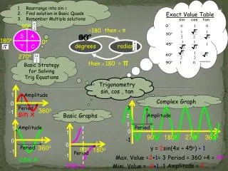
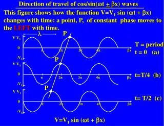
Direction of travel of cos/sin( w t + b x) waves. This figure shows how the function V=V 1 sin ( w t + b x) changes with time: a point, P, of constant phase moves to the LEFT with time. P. l. V V 1 0 -V 1. T = period t = 0 (a) t=T/4 (b) t= T/2 (c).

E N D
Direction of travel of cos/sin(wt +bx) waves This figure shows how the function V=V1 sin (wt + bx) changes with time: a point, P, of constant phase moves to the LEFT with time. P l V V1 0 -V1 T = period t = 0 (a) t=T/4 (b) t= T/2 (c) p 2p 3p 4p bx P V V1 0 -V1 p 2p 3p 4p bx P V V1 0 -V1 p 2p 3p 4p bx V=V1 sin (wt + bx)
Direction of travel of cos/sin(wt +bx) waves This figure shows how the function V=V1 sin (wt - bx) changes with time: a point, P, of constant constant phase moves to the RIGHT with time. P l V V1 0 -V1 T = period t = 0 (a) t=T/4 (b) t= T/2 (c) p 2p 3p 4p bx P V V1 0 -V1 p 2p 3p 4p bx P V V1 0 -V1 p 2p 3p 4p bx V=V1 sin (wt - bx)
P V x Phase Velocity of a Wave on a Transmission Line V=V1 sin (wt - bx) The PHASE VELOCITY of a wave is defined as the velocity of a point of constant phase. For a point of constant phase, V is constant, hence wt+ bx = constant To find the velocity of this constant phase point we must obtain x/t, so differentiate the above w.r.t time, t: w +b x/t = 0 \ PHASE VELOCITY = x/t = +w/b = + v
Substituting for V/t and 2V/t2 in 7: If V = V1 e(jwt+gx)then: Comparing (16) and (17), we see that for our trial function to be a solution: γ2V = (R + jwL)(G + jwC)V => g2= (R + jwL)(G + jwC) (18) Thus V1 e(jwt+gx)is a solution to Equation 7 if: g = + {(R + jwL)(G + jwC)}1/2 (19)
The + sign again indicates the direction the wave is travelling in: the solution with e-gxcorresponds to a forward travelling wave (+x direction) the solution with e+gxcorresponds to a backward travelling wave (-x direction) The general solution is V = V1 e jwt e -gx +V2 e jwt e +gx where V1 and V2 are independent arbitrary amplitudes which depend on the circumstances. -x +x
Thus for the lossless case e+gx=e+ jbx i.e. g is purely imaginary (γ = ±j). In general,g is complex and has both real and imaginary parts: g = +{(R+jwL)(G+jwC)}1/2 = +(a + jb) Hence: e+gx = e+(a+jb)x=e+axe+jbx The factor e+ax operates on the amplitude of the wave, decreasing it exponentially. a is termed the ATTENUATION CONSTANT e+ax gives the amplitude attenuation as the wave travels e+jbxgives the phase change over distance x g is termed the PROPAGATION CONSTANT
For a forward travelling wave: V = V1 e-ax e j(wt-bx) amplitude factor phase factor time variation Voltage V1 x
Part 2 - Characteristic Impedance and Reflections Lecture Topics 4. Current and voltage on a transmission line: Characteristic impedance, ZO Characteristic impedance of general lines Characteristic impedance of lossless lines Reflections on transmission lines Infinitely long transmission lines 5. Transmission line with change of ZO: voltage reflection coefficient Voltage reflection coefficient at an arbitrary distance l from the load ZL 6. Impedances of terminated lines Voltage Standing Wave Ratio (VSWR) Voltage Standing Wave measurement
Example 3.4 - The Heaviside Condition Show that there will be no distortion on a transmission line for which R/L = G/C (the Heaviside Condition), provided L and C do not depend on frequency. Oliver Heaviside (1850 - 1925) English physicist and electrical engineer * Started career as a telegrapher * Nominated for a Nobel Prize * Also known for predicting the "Heaviside Layer" in the atmosphere
Current on a transmission line So far we have mainly considered the voltage on a transmission line: forward backward (i.e.reflected) wave wave V = V1e jwte-gx + V2e jwte+gx where g = {(R+jwL)(G+jwC)}1/2 The instantaneous voltage at any given point is the SUM of the forward and backward wave voltages.
Consider the current, I, in the line – if V is sinusoidal, I must also be sinusoidal (if we are working in a linear system, current is proportional to voltage) hence the total current will have the same form as the total voltage: V = V1e jwte-gx + V2e jwte+gx(1) I = I1 ejwte-gx – I2 e jwte+gx where I1 , I2 are the current amplitudes. N.B. minus sign because the currents are flowing in opposite directions
From the Telegrapher's Equations: But I = I1 ejwte-gx – I2 e jwte+gx , so I/t = jωI1 ejwte-gx – jωI2 e jwte+gx = jwI Hence: Similarly, V = V1e jwte-gx + V2e jwte+gx , so V/x = -γV1e jwte-gx + γV2e jwte+gx Hence: -gV1ejwte-gx + gV2ejwte+gx = -(R + jwL)I
-gV1ejwte-gx + gV2ejwte+gx = -(R + jwL)I Re-arranging for I: where I1 and I2 are the amplitudes of the forward and backward current waves respectively.
i.e. in +x direction V+ - forward voltage wave I+ - forward current wave V- - backward (reflected) voltage wave I- - backward (reflected) current wave i.e. in -x direction
Hence: Note that Zo is NOT per unit length - units are just W. The forward and backward current waves (I+, I-) are related to the respective forward and backward voltage waves (V+, V-) by the CHARACTERISTIC IMPEDANCE, Zo.
LDx LDx LDx LDx To infinity Zo CDx CDx CDx CDx Dx Characteristic Impedance of a Lossless Line For a lossless line R=0 and G=0 hence: In the lossless case, Zo is purely REAL, i.e. resistive ...as deduced in Example 1.3:
≈ Characteristic Impedance of a General Transmission Line If the losses are small, i.e. R << w L and G << w C then it can be shown that Zo can be approximated by: (Derivation of this is at back of handout after tutorial questions – N.B. this derivation is NOT EXAMINABLE)
Note that for a general transmission line Zo will be a complex impedance … unless the Heaviside Condition is met, i.e. unless R/L = G/C. In this case: which is the same as for a lossless line … but the line will NOT be lossless in this case because R g 0 and G g 0.
Some General Points Regarding Characteristic Impedance 1. Note that the characteristic impedance relates the forward voltage wave V+ to the forward current wave I+ OR the backward voltage wave V- to the backward current wave I-:
2. It does NOT relate the TOTAL voltage to the TOTAL current: Except in the special case when there is only a forward wave on the line (i.e. V- = 0 and I- = 0):
3. N.B. Zo is NOT the impedance you would measure simply by connecting the line to an impedance measuring system – this would give you the open-circuit impedance Zoc. We will see later (Example 5.2) that Zo = (ZocZsc)1/2 where Zsc is the short-circuit impedance.
Example 4.1 - Characteristic impedance of a parallel-wire line. Calculate the characteristic impedance of a lossless, air-spaced, two-wire transmission line for which the wire radius is 0.5 mm and the spacing is 5 mm.
Example 4.2 - Characteristic impedance of a coaxial line. A coaxial, lossless transmission line with an inner conductor of diameter 2 mm and internal diameter for the exterior conductor of 7.5 mm is filled with polythene dielectric (εr = 2.56, µr = 1). Calculate the characteristic impedance of the line. ε0= 8.85×10⁻¹² Fm-1 µ0 = 400π×10-9 Hm-1 7.5 mm 2 mm
Reflections on Transmission Lines q Like other waves, voltage and current waves on transmission lines can be reflected. • They are reflected by discontinuities on the line, e.g. the load at the end of the line or a changeover from one type of line to another. • A transmission line with discontinuities will have backward (or reflected) waves when a forward wave is propagated along it. ZL ~
q Consequently the TOTAL voltage and current on the line will be VT = V+ + V- and IT = I+ – I- VT / ITg Zo • The impedance seen by the source (i.e. VT/IT at the input terminals of the line) will depend on the magnitude and phase of these reflections. q Since there is a power flow associated with each of the forward and backward waves, the power delivered to the load at the end of the transmission line will drop if there are reflections. When there are no reflections the power delivered to the load is maximised.
INFINITELY LONG TRANSMISSION LINES If we have a forward wave propagating down a transmission line of finite length, any discontinuities present on the line will give rise to reflections, i.e. backward waves. But for an infinite, uniform transmission line there are no discontinuities and so no reflections - the total voltage and total current at any point on the line (including the input end) will be given by: So the infinite line just looks like a load Zo to the source: I I Zo V V Infinite line with characteristic impedance Zo
How can the reflections be prevented? Previously we have seen that (a) an infinite transmission line of characteristic impedance Zo behaves as an effective load of impedance Zo . (b) there are no reflections on an infinite transmission line. A B finite A length B infinite Zo Zo Zo Zo Hence, for no reflections and maximum power transfer, a line of characteristic impedance Zo should be terminated in a load Zo . In this case the load and line are said to be MATCHED.
Summary q The forward and backward currents are related to the forward and backward voltages by Zo, the CHARACTERISTIC IMPEDANCE. q For a lossless line (R = 0, G = 0) or for one that obeys the Heaviside Condition (R/L = G/C):
q If there is a reflected wave on the line then q Reflected waves are caused by DISCONTINUITIES on a transmission line, e.g. the end of the line or a changeover from one type of cable to another. ZL ~ q There are NO REFLECTED WAVES on an INFINITELY LONG TRANSMISSION LINE.
q An infinitely long transmission line of characteristic impedance Zo looks to the source like a load Zo connected directly to it. q MAXIMUM POWER TRANSFER to the load occurs when there are NO REFLECTIONS ON THE LINE. q To achieve this the load and line must be MATCHED, i.e. the load impedance must be the same as the characteristic impedance of the line. Zo ZL = Zo