Indication of Dimensions and Tolerances
170 likes | 343 Vues
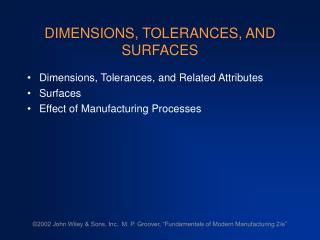
Indication of Dimensions and Tolerances. ISO129-1: 2004 Part 1: General principles. General Principle. All dimensions, graphical symbols and annotations shall be indicated such that they can be read from the bottom or right-hand side (main reading directions) of the drawing

Indication of Dimensions and Tolerances
E N D
Presentation Transcript
Indication of Dimensions and Tolerances ISO129-1: 2004 Part 1: General principles
General Principle • All dimensions, graphical symbols and annotations shall be indicated such that they can be read from the bottom or right-hand side (main reading directions) of the drawing • All dimensional information shall be complete and shown directly on a drawing unless this information is specified in related associated documentation • Each feature or relation between features shall be dimensioned only once • Where all linear dimensions are expressed in the same unit, the unit symbol may be omitted, provided the drawing or associated documentation carries a statement of the unit used
Dimension line Dimension value Terminator Extension line Leader line Reference line Elements of Dimensioning
Coordinate Dimensioning Ordinate Dimensioning
Discussion • Technical Documentation As Design Definition • Good technical documentation should: • Contain just enough information, no more, no less • Unambiguous • Anticipate questions and give direct answers
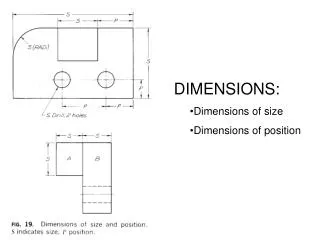
Example - Dimensioning Linear: 9 Radial: 1 Angular: 0 Linear: 5 Radial: 1 Angular: 0 Linear: 5 Radial: 1 Angular: 1
Document only the results, thus can be produced after the form is completed Most of the dimensions are position of edges and corners Requires a lot of calculation to duplicate the form in CAD or physically Dimension to External Features Total 10 dimensions
Document the pattern creation process Dimensions are fundamental geometrical entities such as lengths, widths, radius centre of circles, etc. Can be used for CAD modelling directly, some calculation required for physical modelling Dimension to geometrical datum Total 7 dimensions
Document the cutting and shaping operations Dimensions are measurements taken during physical modelling operations, some of the features no longer exist Can be used for physical and CAD modelling directly Dimension to Boolean Operation Total 6 dimensions
Dimensions should be placed on that view or section which shows the relevant features most clearly Where several features or objects are depicted in close proximity, their relative dimensions should be grouped together, separately, for ease of reading End Note