Download
1 / 18
180 likes | 684 Vues
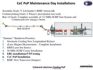
Experience with the 112 MHz 4K SRF Gun for CeC PoP at RHIC. Kevin Smith TTC Meeting at TRIUMF February 6, 2019. Presentation Outline. A Mercifully Brief Overview of CeC PoP Experiment at RHIC (BNL) A Less Brief Overview of the 112 MHz SRF Gun Structure

E N D
Experience with the 112 MHz 4K SRF Gun for CeCPoP at RHIC Kevin Smith TTC Meeting at TRIUMF February 6, 2019
Presentation Outline • A Mercifully Brief Overview of CeCPoP Experiment at RHIC (BNL) • A Less Brief Overview of the 112 MHz SRF Gun Structure • The Main Operational Challenges and Solutions Thereto • Numerous and Persistent Strong Multipacting Barriers • Strong Field Emission • Extremely Brief (No) Summary in the Interest of Brevity
Overview of the CeCPoPExpermient CeC FEL amplifier 3 helical wigglers • The CeCPoP (Coherent electron Cooling Proof of Principle) Experiment at RHIC is a novel, bunched beam cooling experiment at RHIC. PI is V. Litvinenko. • Goal: Strong hadron cooling for a high energy Electron-Ion Collider. • In essence, an extremely wideband stochastic cooling system using an FEL. Common section with RHIC CeC “kicker” 4 quads CeC modulator 4 quads 1.05 MV SRF Gun Dog-leg: 3 dipoles 6 quads Low power Beam dump High power beam dump 2 dipoles 4 quads Bunching RF cavities Low energy transport beam-line with 5 solenoids 13.5 MeV SRF linac
Overview of the CeCPoPExpermient CeC FEL amplifier 3 helical wigglers • The CeCPoP (Coherent electron Cooling Proof of Principle) Experiment at RHIC is a novel, bunched beam cooling experiment at RHIC. PI is V. Litvinenko. • Goal: Strong hadron cooling for high energy Electron-Ion Collider. • In essence, an extremely wideband stochastic cooling system using an FEL. • Two SRF systems: • 112 MHz ¼ Wave Photocathode Gun (4K), Design: 2 MV, Operation: 1.1 MV Dark Current Limit) • LHe tap from a RHIC “DX” magnet with local 4K Quiet LHe source at the cryomodule • 704 MHz 5-Cell Elliptical Linac Cavity (2K), Design: 20 MV, Operation: 13.5 MV (Quench Limit) • Shares 112 MHz LHe tap from RHIC. • Local booster pumps for 2K operation • Integrated 2K Lhe heat exchanger design for noise isolation • Both systems share local compressor for return of warm He gas to RHIC plant. Common section with RHIC CeC “kicker” 4 quads CeC modulator 4 quads 1.05 MV SRF Gun Dog-leg: 3 dipoles 6 quads Low power Beam dump High power beam dump 2 dipoles 4 quads Bunching RF cavities Low energy transport beam-line with 5 solenoids 13.5 MeV SRF linac
112 MHz ¼ Wave Photocathode Gun • Before I talk about the Cavity behavior and experiences … • Excellent results as a Photocathode Gun • World record bunch charge for an SRF Gun • 10.7 nC per bunch maximum achieved • Record low normalized emittance: 0.32 mm mrad at 0.5 nC • QE lifetime from one to two months • Room temperature water cooled cathode (i.e. not cold) • Requires automatic He blowout system in case of water flow failure
112 MHz ¼ Wave Photocathode Gun Field Probe RF coupling to Field Probe is via this coaxial structure. Qext depends on the position of the cathode stalk.
112 MHz ¼ Wave Photocathode Gun RF coupling to Field Probe is via this coaxial structure. Qext depends on the position of the cathode stalk.
112 MHz ¼ Wave Photocathode Gun FPC Structure • The coaxial FPC also acts as the cavity tuner, and thus Qext and fres are coupled. • BW1/2 at Qext = 1E7 is 5.6 Hz.
Multipacting was the Most Persistent Issue • The cavity exhibits several hard MP levels at 2kV, 22 kV, 30 kV, and 40 kV. • Others at higher voltages in FPC and Cathode Stalk structures. • This is life in a system with a multiplicity of coaxial structures. • These proved to be difficult to condition in general, and impossible to condition with a live (CsK2Sb) photocathode inserted. • Cathode QE will be annihilated by MP conditioning – extremely sensitive to vacuum excursions. • Once MP occurs, it often “hardens” the MP barrier, requiring some “rest” period prior to attempting turn on again. • 10 min to overnight, depending on “integrated” MP activity. • Jumping over (through) MP requires strong coupling (low Qext) and maximum RF power. • But if the MP barrier holds, strong vacuum activity and “hardening” of the barrier. • Operating voltage (~ 1.1 MV CW) requires med-high Qext due to RF power limitation (4kW – originally 1kW) and FPC power dissipation. • Susceptible to dropping into MP at or on way up to operating voltage. • Solution • LLRF system employs a combination of PLL (for turn on) and GDR modes (for regulated operation). • Provides a “straight forward” way to accommodate the coupling between Qext and fres. • Add LLRF “trap” to detect MP and cut drive to avoid prolonged MP. • Automated script to coordinate turn on through to operating point.
Example of Cavity Turn On Attempt with Strong MP • Four repeated attempts to turn on result in getting stuck at 22 kV MP barrier. • Attempts last only 20ms, controlled by LLRF MP trap code. • Prevents significant energy deposition => vacuum activity which would kill cathode QE. Successful jump through 22 kV MP barrier. • Example • Lengthen period between attempts from ~ 20 min to ~ 40 min => 5th attempt = successful turn on. • Cathode QE not impacted by turn on attempts as MP related vacuum activity is kept minimal. Failure to achieve voltage in 20 ms results in turn off of drive. 1 kV turn on (2.3 kV MP level just above) to allow PLL to lock on to cavity resonance.
Multipacting Well Studied and Understood Now • Irina Petrushina (PhD student of V. Litvinenko) did a very thorough study of multipacting in the structure, with modeling and simulations that matched very well with observed barriers. Employed CST, MultP-M, ACE3P – Track3P (best approach). • Also developed an equivalent circuit model integrating the resonant multipacting avalanche buildup, which provides reasonably quantitative predictions of RF power and coupling required to punch through a given MP barrier. 40 kV MP 28 kV MP
Field Emission Limits Operating Voltage due to Dark Current • Strong field emission which has required multiple (successful) rounds of pulsed conditioning and He conditioning. • Why? • Cavity was unquestionably contaminated prior to and/or during installation. • General cavity and beamline installations were not up modern “SRF Clean” standard. • Multiple insertions and retractions of a cathode structure which makes metal-metal contact “near” the SRF active surfaces likely do not help maintain clean conditions. • It is not clear (to me at least) whether any active cathode material has contaminated the Nb surface(s). It is hypothesized that it has contributed to MP behavior. • Result: • Can’t operationally run cavity higher than about 1.1 MV CW (design is 2.0 MV). • Fortunately the He return compressor can handle ~ 10 g/s, so we can push hard when attempting to condition (we’ve pegged the mass flow gauge at 10 g/s). • In general, if field emission becomes excessive at 1.0MV, we can recondition and gain substantial improvement within a shift or two of effort. • System has a permanent He processing system attached and available when needed. • Operation at 1.0 MV – 1.1 MV has been sufficient to produce very high charge, high quality bunches. ? ?
Field Emission Change from End of Run to Start of Next Run • Typical x-ray level at end of Run 17 (June 2017) was about 300 mRem/hr at 1.05 MV. • Typical x-ray level at start of Run 18 (Feb 2018) was about 2000 mRem/hr at 0.9 MV. • Also, lots of cathode stalk activity during the shutdown. • Doesn’t help to vent beamline just downstream. • Component replacement. • We lose LHe when RHIC cryo shuts down. • Warmup redistributes adsorbed gases.
Field Emission Processing – 40ms, 25ms, 1Hz pulsing w/ He 40 ms pulses 20 ms pulses ~ 1.2 Rem/hr at 1.7 MVpk, roughly 2-3 % duty cycle (w.r.t. peak voltage, peak x-ray) 40 ms pulse
Field Emission HPPP w/ Helium Processing Results After processing Before processing