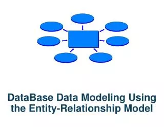
DataBase Data Modeling Using the Entity-Relationship Model
DataBase Data Modeling Using the Entity-Relationship Model. Data Modeling. Process of creating a logical representation of the structure of the database The most important task in database development. The Data Model. A data model is a plan, or blueprint, for a database design .

DataBase Data Modeling Using the Entity-Relationship Model
E N D
Presentation Transcript
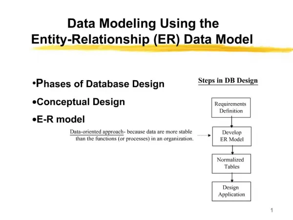
Data Modeling Process of creating a logical representation of the structure of the database The most important task in database development
The Data Model A data model is a plan, or blueprint, for a database design. A data model is more generalized and abstract than a database design. It is easier to change a data model than it is to change a database design, so it is the appropriate place to work through conceptual database problems.
The Entity-Relationship model is a set of concepts and graphical symbols that can be used to create conceptual schemas The Entity Relationship Model
Versions/Evolution of the E-R Model • Original E-R model by Peter Chen (1976) • Extended E-R model (1986): added subtypes, now the most widely used E-R model, and what we will use in IS431 • Information Engineering/IE model (also called the Crow’s Foot model) developed by James Martin in 1990 • IDEF1X (1994) : national standard by the National Institute of Standards and Technology • Additionally: • Unified Modeling Language (UML) Style E-R Models • Semantic Object Data Models (SOMs)
Entities (really entity sets) • Attributes • Relationships • Identifiers The Four Major Components of the Entity Relationship (E-R) Model
An Example of an E-R Diagram The notation will be explained…
The Geometric Symbols in an E-R Model • Entities are represented by rectangles. • Attributes are represented by ovals, that are connected to the entity by a straight line. • Relationships are represented by diamond shaped symbols. • The name of the entity (class) or attribute or relationship is usually placed inside the symbol used for that object. (Sometimes, with relationships, the name is placed adjacent.)
Entities and Entity Sets • An entity set (or class) is something that can be identified and the users want to track • Entity class is a collection of entities described by the entity format in that class • Entity instance is the representation of a particular entity • There are usually many instances of an entity in an entity class • Consider an entity class STUDENT • An entity instance would be a particular student in the entity class, for example, Matthew Jones might be an entity instance • A general notational convention is to CAPITALIZE the entity set’s name
An entity set/class is represented by a rectangle with the name of the entity set/class in the rectangle. STUDENT Representing Entities (Entity Sets) in an E-R Model
Attributes • Description of the entity’s characteristics • All instances of a given entity class have the same attributes • Composite attribute: attribute consisting of the group of attributes • Multi-value attributes: attribute with more than one possible value
Representing Entities and Their Attributes Method 1: Place the entity name in a rectangle, and the attributes as ovals/ellipses attached to the rectangle. Method 2: Place the entity name at the top of a portrait-shaped rectangle, and place the attributes below the entity name in a rectangle.
A Student Entity Set With Three Attributes (Using Ovals/ellipses) Lastname Student-id Firstname (Can you describe what the entity set STUDENT would look like, if we used Method 2)? STUDENT
Attributes are the properties that define the entity's characteristics • The E-R model assumes that all instances of a given entity set have the same attributes. • So, for the ER model in the prior slide for STUDENT, instances of STUDENT, such as Henry Gordon, Joyce Johnson, Jeffrey Chan, etc, will each have a Student-ID, a Lastname and a Firstname attribute. Review of Attributes
Identifiers are one or more attributes of entity instances which serve to name, or identify, the entity instance. • For the STUDENT entity set, identifiers are Student-id and the composite identifier (Last-name, First-name). • Composite identifiers are identifiers that consist of two or more attributes • Identifiers are either Unique (identifies one and only one entity) or Non-Unique (identifies a set of entities). • We often refer to a Unique Identifier as the Primary Key of a table (relation). Identifiers
Attributes will also have a domain. • The domain is the attribute's set of possible values. • The domain of the attribute "Grade Point Average" is a real number between 0 and 4. • The domain of the attribute "Gender" consists of only two possibilities, M or F (or some other equivalent code). • Attributes may share a domain. • The attribute PROFESSOR_AGE and STUDENT_AGE share the domain of all possible ages. Attributes & Domains
Variations on Displaying Entity Sets and Attributes in an Entity Set Depending on the size of our ER model, we might display the entity set name and ALL of the attributes, or the entity set name and the identifier, or just the entity set name:
A Single-Valued Attribute can have only a single value. • Example: Age is a single valued attribute of the entity person, because a person can have only one age. • A composite attribute is a logical grouping of single-valued attributes. • Example: The composite attribute Address consists of the group (Street, City, State, Zip). Classification of Attributes By Allowable Values
AMulti-Valued Attribute can have many values. • Example: PackageExpertise is a multiple valued attribute of the entity person, because a person may have expertise in many packages (WordPerfect, Excel, Photoshop, Access, Powerpoint, AutoCad, MathCad, etc.) • A multi-valued attribute may also be composite. An example would be, assuming we allowed multiple phone numbers for an entity, Phone (area code, number) • In an E-R model, Multiple Valued Attributes are shown by a double line (or a bold line) connecting the attribute to the entity (entity class). Classification of Attributes By Allowable Values - Continued
A Multi-Valued Attribute “Color” Model Year Manuf Color Car-id Engine Primary Key (Unique Identifier) CAR
For the original entity, create additional new attributes, one for each of the original composite attributes components. • Thus, the composite attribute Color will be split into new attributes: Topcolor, Bodycolor and Trimcolor, all linked to the entity class Car. Translating E-R models with Composite Attributes into a Relational DBMS
Bodycolor Year Model Topcolor Manuf Trimcolor Car-id Engine Splitting the Composite Attribute into New Attributes CAR
A Derived Attribute does not physically exist within the database, but is derived (computed) by an algorithm or computation. • Example: A person's AGE attribute can be derived by subtracting the date of birth (DOB) from the current date. • Example: Total cost can be derived by multiplying quantity ordered by unit price. • A Derived Attribute is indicated in an E-R Model by a dotted line connecting the attribute to the entity. Derived Attributes
A Derived Attribute E-num E-age E-dob EMPLOYEE
A relationship is an association between entities: • Relationship classes: associations among entity classes • Relationship instances: associations between entity instances • Relationships are represented by diamond-shaped symbols, connecting the entities in the relationship (the entities are referred to as the participants in the relationship). • In the original Entity-Relationship model. relationships were allowed to have attributes, but not in the extended E-R model today. Relationships in an E-R Model
COURSE PROFESSOR TEACHES What would be a relationship instance in this case? A Relationship Class Between a Professor Entity Set/Class and a Course Entity Set/Class
The degree of a relationship is the number of associated entity sets (participants) in the relationship. • A UNARY RELATIONSHIPexists when an association exists within a single entity • A BINARY RELATIONSHIP exists when two entities(participants) are in the relationship. • A TERNARY RELATIONSHIP exists when three entities (participants) are in the relationship. The DEGREE of a Relationship
BINARY UNARY PROFESSOR TEACHES PREREQ COURSE COURSE
FATHER TERNARY PARENT CHILD MOTHER
One to One • Abbreviated as "1:1" • One to Many • Abbreviated as "1:N" • Many-to-Many • Abbreviated as "N:M" THREE TYPES OF BINARY RELATIONSHIPS
AUTO 1:1 AUTO-ASSIGNMENT STUDENT 1:N DORMITORY DORM-OCCUPANT N:M STUDENT CLUB STUDENT-CLUB EMPLOYEE
No employee has more than one auto assigned to him/her. • No automobile is assigned to more than one employee. The 1:1 AUTO-ASSIGNMENT (BINARY) RELATIONSHIP
A Dormitory will have "many" student occupants (where "many" could be any number: 0, 1, 5, 72, etc.). • A Student will be an occupant of (at most) ONE dormitory. • The positions of the 1 and the N are significant. The 1 refers to the dormitory side of the relationship, and the N refers to the student side of the relationship. The 1:N DORM OCCUPANT RELATIONSHIP
A student can be a member of "many" (any number of) clubs. • A club will have "many" (any number of) student members. The N:M STUDENT-CLUB RELATIONSHIP
An Alternative (“Crow’s Foot) Notation for Denoting the “Many” Part of the Relationship DORM-OCCUPANT STUDENT DORMITORY CLUB STUDENT-CLUB STUDENT The “many” relationship cardinality is denoted by placing crow’s feet (two short diagonal lines) on the many side of the relationship.
RULE: The numbers inside the relationship diamond show the maximum number of entities which can occur on one side of the relationship. • These relationships are often called "HAS A" relationships (because, for instance, a student 'has a' dormitory). We will contrast this later with "IS A" relationships. The Maximum Cardinality of a Relationship
Cardinality Cardinality means “count,” and is expressed as a number. Maximum cardinality is the maximum number of entity instances that can participate in a relationship. Minimum cardinality is the minimum number of entity instances that must participate in a relationship
Parent and Child Entities • In a one-to-many relationship: • The entity on the one side of the relationship is called the parent entity or just the parent. • The entity on the many side of the relationship is called the child entity or just the child. • In the figure below, EMPLOYEE is the parent and COMPUTER is the child:
HAS-A Relationships • The relationships we have been discussing are known as HAS-A relationships: • Each entity instance has a relationship with another entity instance: • An EMPLOYEE has one or more COMPUTERs. • A COMPUTER has an assigned EMPLOYEE.
Describing the Minimum Number of Entities to Participate in a Relationship • The maximum cardinality denotes the maximum number of entities that can be involved in a relationship. • As described previously, this is usually denoted by the two values inside the diamond, separated by a colon, such as 1:N • We need a methodology to also describe the minimum cardinality in a relationship • For instance, should we require that a student be assigned to some dormitory, or should we make this optional for a student (we have to model the rules of the college!)
A participating entity in a relationship is either OPTIONAL or MANDATORY • Participation is OPTIONAL if one entity occurrence does not REQUIRE a corresponding entity occurrence from the other entity set, in a particular relationship. Relationship Participation: Case 1 - Optional Participation
An Example of Optional Participation CLASSES PROFESSORS 0 1:1 TEACH • Example: At Marvel College, research professors are employed who work only on research projects and do no teaching, so these professors do not teach any classes. • We show an OPTIONAL entity by drawing a small circle on the side of the entity set which is to be optional.
Participation is MANDATORY in a relationship if one entity occurrence DOES require a corresponding entity occurrence in the other entity set, in a particular relationship. A mandatory participation implies a (non-zero) minimum cardinality. Relationship Participation: Case II - Mandatory Participation
Example of Mandatory Participation | 0 PROFESSORS 1:1 1:N CLASSES • We specify, in our E-R diagram, a mandatory participation by placing a small (usually vertical) line across the relationship line. • Example - Marvel College requires that each class be taught by one, and only one, professor
STUDENT 1:N 0 The DORM-OCCUPANT Relationship with Minimum Cardinality Shown DORMITORY