Database Theoretic Basis Entity Relationship (E-R) Modeling
Database Theoretic Basis Entity Relationship (E-R) Modeling. Developing an E-R Diagram. The process of database design is an iterative rather than a linear or sequential process. It usually begins with a general narrative of the organization’s operations and procedures.

Database Theoretic Basis Entity Relationship (E-R) Modeling
E N D
Presentation Transcript
Database Theoretic Basis Entity Relationship (E-R) Modeling
Developing an E-R Diagram • The process of database design is an iterative rather than a linear or sequential process. • It usually begins with a general narrative of the organization’s operations and procedures. • The basic E-R model is graphically depicted and presented for review. • The process is repeated until the end users and designers agree that the E-R diagram is a fair representation of the organization’s activities and functions.
1 works for N department 1 1 controls manages employee 1 N supervisee supervisor N N M supervision 1 works on 1 project dependents of N dependent partial constraint total constraint
ER Modeling • Entity Relationship Modeling is a process used to help us understand and document the informational requirements of a system. - a system at your university, college, or school needs to keep information about students including their names, addresses, birth dates, courses, enrollments, grades, etc. - these things are documented in the model - we create a drawing called an Entity Relationship Diagram, or ERD
Eventually: • We create a physical model in some (relational) database management system (DBMS) • We translate the ER Model into a relational database • Suppose we know of four student entities and two courses entities. For example, four students named John, Amelia, Lee, and April, and two courses “Intro to Art” and “Intro to History”. Information about these is listed below.
Students Name Id# Phone John 184 283-4984 Amelia 337 838-3737 Lee 876 933-2211 April 901 644-3838 Course Name Course# Dept Intro to Art 661 Art Intro to History 765 History
John • Amelia • Lee • April We can represent these two sets of entities using set diagrams. Intro to Art Intro to History set of students set of courses Relationships describe how entities relate to one another
Suppose we have the two courses and four students listed previously. Suppose also that - John and Amelia are enrolled in Intro to Art - John and Lee are enrolled in Intro to History - April is not enrolled in any course. Below, we depict a relationship set and show the four instances of an enroll in relationship.
John • Amelia • Lee • April Intro to Art Intro to History
Note there are four instances of enroll in. Each Instance involves exactly two entities: a student entity and a course entity. Because each instance of enroll in involves two entities, it is referred to as a binary relationship. Binary relationships will be the focus of most of our discussions.
m Enroll-in n Students Course An example of an Entity Relationship Model: Entities are indicated using rectangular shapes, and relationships between entities are shown with a diamond shape on a line connecting the entities. Entity sets are shown with a rectangular shape. Relationship sets are shown with a diamond shape. The "m" indicates that one course may have many students enrolled in it. The "n" indicates that one student may have enrolled in many courses.
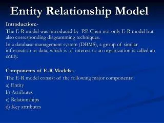
The ER model was introduced by Peter Chen in his paper The Entity-Relationship Model--Toward a Unified View of Data (ACM Transactions on Database Systems, Vol. 1, No. 1, 1976). This paper is one of the most cited papers in the computer field, and has been considered one of the most influential papers in computer science.
ERD symbols Entity Weak entity Relationship Identifying relationship name Attribute Key attribute name
ERD symbols Composite attribute name Derived attribute name Mutlti-valued attribute name Partial participation Total participation Cardinality 1 n N
With attributes, etc: name number location 1 fname lname works for minit N department salary address name sex 1 number of employees startdate 1 ssn controls manages employee 1 bdate N supervisor hours N degree supervisee M supervision works on 1 project dependents of name number location N dependent relationship name sex birthdate