Overview of Standard Combinational Modules in Digital Design: Decoder, Encoder, Mux, and More
This lecture covers essential standard combinational modules crucial for digital circuit design. It explains the functionality and applications of decoders, encoders, multiplexers (Mux), demultiplexers (DeMux), shifters, adders, and multipliers. Key concepts include how decoders decode addresses to select outputs, encoders that encode addresses, the role of Mux in data selection, and DeMux for data direction. Also discussed are logic diagrams, examples, and configurations for implementing these modules effectively in digital systems.


Overview of Standard Combinational Modules in Digital Design: Decoder, Encoder, Mux, and More
E N D
Presentation Transcript
CS 140 Lecture 12Standard Combinational Modules Professor CK Cheng CSE Dept. UC San Diego
Part III - Standard Combinational Modules • Decoder: Decode address • Encoder: Encode address • Multiplexer (Mux): Select data by address • Demultiplexier (DeMux): Direct data by address • Shifter: Shift bit location • Adder: Add two binary numbers • Multiplier: Multiply two binary numbers
Arbiter Data 1 P1 Mux, Memory Bank Data Address 1 P2 Demux n-m Mux Address 2 Address n m 2m Address k Decoder Data k Pk Interconnect: Decoder, Encoder, Mux, DeMux
1. Decoder • Definition • Logic Diagram • Application (Universal Set) • Tree of Decoders
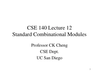
1. Decoder: Definition EN (enable) y0 y1 y7 0 1 2 3 4 5 6 7 I0 0 . . 1 I1 I2 2 n to 2n decoderfunction: 2n outputs 23= 8 n inputs n= 3 yi = 1 if En= 1 & (I2, I1, I0 ) = i yi= 0 otherwise
1. Decoder: Definition • N inputs, 2N outputs • One-hot outputs: only one output HIGH at once
Decoder: Logic Diagram yi = mi En En y0 = 1 if (I2, I1, I0 ) = (0,0,0) & En = 1 I0’ I1’ y0 I2’ I0’ I1’ y1 I2 . . I0 y7 = I2I1I0En I1 y7 I2
En y0 y1 . . y7 0 1 2 3 4 5 6 7 c I0 I1 b a I2 Decoder Application: universal set {Decoder, OR} Implement functions f1(a,b,c) = Sm(1,2,4) Example: f2(a,b,c) = Sm(2,3), and f3(a,b,c) = Sm(0,5,6) with a 3-input decoder and OR gates. y1 y2 y4 f1 y2 y3 f2 y0 y5 y6 f3
Decoders • OR minterms
Tree of Decoders Implement a 4-24 decoder with 3-23 decoders. y0 y1 y7 0 1 2 3 4 5 6 7 d I0 c I1 b I2 y8 y9 y15 0 1 2 3 4 5 6 7 I0 I1 I2 a
Tree of Decoders Implement a 6-26 decoder with 3-23 decoders. En En y0 D0 I2, I1, I0 y7 y8 I5, I4, I3 D1 I2, I1, I0 y15 … … y56 D7 I2, I1, I0 y63
2. Encoder • Definition • Logic Diagram • Priority Encoder
2. Encoder: Definition En I2n-1…I0 yn-1 …y0 A Encoder Description: En At most one Ii = 1. (yn-1,.., y0 ) = i if Ii = 1 & En = 1 (yn-1,.., y0 ) = 0 otherwise. A = 1 if En = 1 and one i s.t. Ii = 1 A = 0 otherwise. I0 0 1 2 3 4 5 6 7 y0 0 1 2 y1 y2 I7 3 outputs A 8 inputs
Encoder: Logic Diagram En y0 I1 I3 I5 I7 En y1 I2 I3 I6 I7
Encoder: Logic Diagram En y2 I4 I5 I6 I7 En A I0 I1 . . I6 I7
Priority Encoder: Definition Description: Input (I2n-1,…, I0), Output (yn-1 ,…,,y0) (yn-1 ,…,,y0) = i if Ii = 1 & En = 1 & Ik = 0 for all k > i (high bit priority) or for all k< i (low bit priority). Eo = 1 if En = 1 & Ii = 0 for all i, Gs = 1 if En = 1 & i s.t. Ii = 1. En E (Gs is like A, and Eo tells us if enable is true or not). I0 0 1 2 3 4 5 6 7 y0 0 1 2 y1 y2 I7 Eo Gs
Priority Encoder: Implement a 32-input priority encoder w/ 8 input priority encoders (high bit priority). En I31-24 y32, y31, y30 Gs Eo I25-16 y22, y21, y20 Gs Eo I15-8 y12, y11, y10 Gs Eo I7-0 y02, y01, y00 Gs Eo