Download
1 / 50
500 likes | 622 Vues
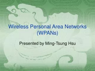
IEEE 802.11 QoS MAC Enhancements Joint Proposal AT&T, Lucent, ShareWave. Why Add QoS Support to the 802.11 MAC?. Why is it necessary to add new functionality within the 802.11 MAC sublayer to support QoS over wireless links? Higher layers assume that a LAN rarely loses or delays packets .

E N D
IEEE 802.11 QoS MAC Enhancements Joint Proposal AT&T, Lucent, ShareWave AT&T, Lucent, ShareWave
Why Add QoS Support to the 802.11 MAC? • Why is it necessary to add new functionality within the 802.11 MAC sublayer to support QoS over wireless links? • Higher layers assume that a LAN rarely loses or delays packets. • WLAN PHY error rates are 3+ orders of magnitude greater than wired. • So 802.11, unlike other 802 LANs, retransmits unacknowledged frames. • Retrys cause unpredictable delays of tens to hundreds of milliseconds, and often block transmission of subsequent, queued frames. • Wireless links incur very high per-packet MAC & PHY overhead: • 802.3 framing+gap adds 3.2% to a 1500-octet MSDU. • 802.11B (11Mb/s) framing+gaps+Ack adds 32.6% (50.0% with RTS/CTS). • CSMA/CA collisions and backoffs reduce usable bandwidth as the offered load in a BSS increases. • Switching hubs cannot be used to isolate STA-to-STA traffic over wireless links. • QoS-aware coordination can reduce overhead, prevent collisions and prioritize queued frames to meet delay and jitter bounds. AT&T, Lucent, ShareWave
What is Being Added? • This joint proposal provides new services and frame formats to support higher-layer, end-to-end QoS mechanisms: • A QoS Data Service supporting Virtual Streams (VS) with specified QoS parameter values and including priority, data rate, delay and jitter bounds. • An enhanced PCF allocates bandwidth to virtual streams and asynchronous traffic: • New forms of CF-poll allow precise dynamic control with reduced overhead. • Persistent transmission scheduling provides QoS-friendly power save operation. • An adaptive technique prevents interference among overlapping, point-coordinated BSSs operating on the same channel, while allowing non-interfering transfers to occur in parallel, even when the overlapping BSSs are not part of the same ESS. • A centralized Contention Control (CC) facility is more efficient than DCF contention for sending Reservation Request (RR) frames for new bandwidth allocations. • New management frame subtypes support QoS and BSS overlap management. • New data frame subtypes for "stream data" contain a VS identifier (VSID) field. • New acknowledgement policies reduce overhead for many stream data transfers. • Direct station-to-station transfers are permitted in a QoS-capable BSS (QBSS). • A dynamic wireless repeater function can extend the spatial coverage of a QBSS. AT&T, Lucent, ShareWave
How Does the QoS Support Operate? • This joint MAC proposal is based upon an enhanced point coordination function that understands QoS-related parameters: • Each enhanced station (ESTA) has a classification entity (CLSE) above the MAC to identify the virtual streams for incoming MSDUs. • Each QoS-supporting BSS (QBSS) is controlled by an enhanced access point (EAP) with an enhanced point coordinator (EPC). • The EPC includes a time allocation management entity (TAME) that allocates transmission opportunities (TXOPs) to ESTAs. • TXOPs have defined starting times and maximum durations. ESTAs make local decisions about which MPDUs to transmit during each TXOP. • A QBSS may have ESTA(s) that operate as bridge-portals (BPs) to allow alternate or multiple points of connection to the infrastructure. • Spatial coverage of a QBSS may be extended by dynamically-activated Repeater Point Coordinators (RPCs). AT&T, Lucent, ShareWave
Compatibility • The proposed QoS functions are a direct extension of existing 802.11 functions: • Reserved bits in existing frame formats are defined for the new functions: • Capability Information bit 8 indicates QoS (and EPC in conjunction with CF bits). • Data subtype bit 7 is set to 1 to indicate "stream data" in QoS MPDUs. • Duration/ID bits 0-13 contain QoS control information during the CFP (msb=10). • Several QoS-related Control and Management frame subtypes are defined. • Existing stations can communicate in a QBSS during the CP (under DCF). • Existing CF-pollable stations may be polled by an EPC during the CFP. • The BSS overlap mitigation procedure is effective (but non-optimal) for reducing interference between QBSSs and a non-QoS BSSs. • All stations must be CF-conformant as specified in IEEE 802.11-1999. • The proposed QoS support is intended to operate with existing authentication and privacy mechanisms, as well as any enhanced security facilities adopted as part of 802.11E. AT&T, Lucent, ShareWave
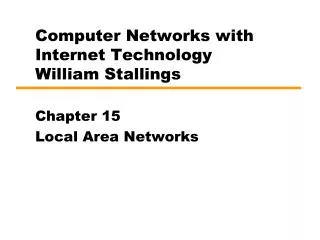
Centralized versus Distributed Contention • Fully distributed (without a PC): • AP needs to contend, especially severe for asymmetric traffic loads. • A large data burst needs to break down into a large number of MPDUs, each of which has to contend for transmission (resulting in lots of contentions if there are other data STAs sending data) and is likely to transmit beyond the TBTT (bad for other time-bounded frames). • Backoff for collision resolution is based on the contention outcome of the backoff STA itself, and is far from being optimal. AT&T, Lucent, ShareWave
Centralized versus Distributed Contention (Continued) • Partially distributed (with a PC): • Contention and backoff under the DCF has the same shortcomings as noted above. • Centrally controlled: • Any data burst needs to contend at most once to send a small RR frame, and its transmission is completely under the control of the PC (not getting impatient), with the contention never going beyond the TBTT. • Collision resolution is based on the contention outcome of all STAs and can be optimised. • Significantly improved data access delay and channel throughput performance. AT&T, Lucent, ShareWave
Stream Service Interfaces AT&T, Lucent, ShareWave
Stream Service Interfaces • QoS-driven virtual stream service interfaces reference model • Relationships between higher and lower layers • Transformation of WLAN into QoS network within end-to-end QoS context • RSVP/SBM roles--Macro management • VDS: Sender outside BSS, receiver inside BSS • VUS: Sender inside BSS, receiver outside BSS • VSS: Sender & receiver inside BSS • QoS parameters • MAC (PCF) roles--Micro management • Queuing discipline needed for QoS support even for point-to-point transmissions • Transmission time allocation to VSs (up, down, side) AT&T, Lucent, ShareWave
DSBM LLC CLSE E- SME SME MAC MLME TAME PLCP 2 PLME PMD 5 1 3 4 4 2 4 5 3 5 1 4 3 5 5 EPC SBM LLC E-MLME CLSE SME MAC MLME TAME PLCP PLME PMD VS Service Interfaces Reference Model SBM = Subnet Bandwidth Manager DSBM = Designated SBM CLSE = Classification Entity TAME = Time Allocation Management Entity SME = Station Management Entity E-SME = Enhanced SME MLME = MAC Sublayer Management Entity E-MLME = Enhanced MLME PC = Point Coordinator VS = Virtual Stream VDS = Virtual Down Stream VUS = Virtual Up Stream VSS = Virtual Side Stream End-to-end QoS signaling messages End-to-end QoS signaling messages QoS values & classifiers VS’s & VSID’s VSID’s & classifiers VSID’s & QoS values VS Update VS Update SBM Frame Tx LLC E-MLME CLSE CLSE TAME SME MAC MLME VS Operation Classifiers QoS values TAME QoS values (designated by VSID) PLCP PLME PMD NON-EPC ESTA x NON-EPC ESTA y AT&T, Lucent, ShareWave
DSBM LLC CLSE E- SME MAC TAME 2 EPC 5 5 1 2 1 4 3 4 3 SBM LLC E-MLME CLSE MAC TAME RSVP/SBM--Only Receiver Inside BSS Path messages (From sender) Resv messages (To sender) Virtual Down-Stream (VDS) Setup: 1. DSBM extracts QoS values and classifier from new Path/Resv messages for a down-stream session, and makes admission decision on the session (accounting for the channel status update from MAC). 2. If the session is admitted, E-SME establishes a VSID for a VDS to serve the session. 3. E-SME passes VSID and classifier for addition to classification table at CLSE (for frame classification). 4. E-SME passes VSID and QoS values for addition to TAME (for bandwidth allocation). 5. E-SME has MLME send a management frame, VS Update, containing VS Operation (add VDS) and QoS values for the down-stream session. Virtual Down-Stream (VDS) Modification: 1. DSBM extracts modified QoS values from Path/Resv messages for an admitted down-stream session and decides whether or not to honor them. 2. If yes, E-SME updates TAME with new QoS values for the established VSID, and has MLME send another VS Update, containing VS Operation (update VDS) and new QoS values for the session. Virtual Down-Stream (VDS) Teardown: 1. DSBM extracts classifier from Path/Resv teardown messages or timeout indication for an admitted down-stream session. 2. E-SME matches classifier to VSID established for the session. 3. E-SME passes VSID and classifier for deletion from classification table at CLSE. 4. E-SME passes VSID for deletion from TAME. 5. E-SME has MLME send another VS Update, containing VS Operation (delete VDS) for the session. QoS values & classifier Resv messages (From receiver) Path messages (To receiver) VS & VSID VSID & classifier VSID & QoS values VS Update Data traffic direction--down stream--for which DSBM makes admission decision VS Operation QoS values NON-EPC ESTA x AT&T, Lucent, ShareWave
DSBM LLC CLSE E- SME MAC TAME 2 EPC 3 2 4 3 5 4 5 1 1 SBM LLC E-MLME CLSE MAC TAME RSVP/SBM--Only Sender Inside BSS Path messages (To receivers) Resv messages (From receivers) QoS values & classifier For confirmation only Virtual Up-Stream (VUS) Setup: 1 & 2 same as for VDS setup. 3. E-SME passes VSID and QoS values for addition to TAME (for bandwidth allocation). 4. E-SME has MLME send a management frame, VS Update, containing VS Operation (add VUS), classifier, and QoS values for the up-stream session. 5. Upon receiving the management frame, the addressed ESTA’s E-MLME acts like EPC’s E-SME for its own CLSE and optionally TAME. Virtual Up-Stream (VUS) Modification: 1 DSBM extracts modified QoS values from Path/Resv messages for an admitted up-stream session and decides whether or not to honor them. 2. If yes, E-SME updates TAME with new QoS values for the established VSID, and has MLME send another VS Update, containing VS Operation (modify VUS) and new QoS values for the session. 3. Upon receiving the new management frame, the addressed ESTA’s E-MLME updates its TAME with new QoS values for the established VSID. Virtual Up-Stream (VUS) Teardown: 1 & 2 same as for VUS teardown. 3. E-SME passes VSID for deletion from TAME. 4. E-SME has MLME send another VS Update, containing VS Operation (delete VUS) and classifier for the up-stream session. 5. Upon receiving the new VS Update, the addressed ESTA’s E-MLME passes VSID and classifier for deletion from classification table at its CLSE/TAME. Path messages (From sender) Resv messages (To sender) VS & VSID VSID & classifier VSID & QoS values VS Update Data traffic direction--up stream--for which DSBM makes admission decision VS Operation Classifier QoS values NON-EPC ESTA x AT&T, Lucent, ShareWave
2 5 5 5 5 4 3 1 1 2 3 4 5 4 RSVP/SBM--Sender/Receiver Inside BSS Data traffic direction--up stream--for which DSBM makes admission decision DSBM QoS values & classifier For confirmation only Resv messages (From receiver) Path messages (To receiver) LLC Path messages (From sender) Resv messages (To sender) CLSE VS & VSID E- SME SME MAC MLME VSID & classifier TAME PLCP Virtual Side-Stream (VSS) Setup, Modification, and Teardown: Similar to those for Virtual Up-Stream. VSID & QoS values PLME PMD EPC VS Update VS Update SBM SBM LLC LLC E-MLME E-MLME CLSE CLSE SME SME MAC MLME MAC MLME VS Operation Classifier QoS values TAME TAME PLCP PLCP PLME PLME PMD PMD NON-EPC ESTA x NON-EPC ESTA y AT&T, Lucent, ShareWave
Virtual Stream Management Interface • Virtual Stream Update Service Primitives • MLME-VSUPDATE.request (VSID, VS Action, VS Subaction,QoS Parameter Set, Frame Classifier, VS Update Failure Timeout) • Sent by DSBM to cause transmission of a VS-Update management frame with the specified parameter values. The QosParameterSet and FrameClassifier are sent using information elements. • MLME-VSUPDATE.confirm (Result Code) • Confirms transmission of VS-Update managagement frame. • MLME-VSUPDATE.indication (VSID, VS Action, VS Subaction, QoS Parameter Set, Frame Classifier) • Informs SBM of reception of a VS-Update management frame. • Channel Status Service Primitive • MLME-CHANNEL-STATUS.indication (BWAvailable, BWUsed) • Generated by TAME once per superframe to inform DSBM of the amounts of channel bandwidth available and in use for QoS transport. AT&T, Lucent, ShareWave
MAC Data Services • Two services are available at the MAC SAP • Asynchronous Data Service, as defined in IEEE 802.11-1999 • QoS Data Service, for MSDUs belonging to virtual streams • MAC Data Service Primitives • MA-UNITDATA.request (source address, destination address, routing information, data, priority, service class) • MA-UNITDATA.indication (source address, destination address, routing information, data, reception status, priority, service class) • MA-UNITDATA-STATUS.indication (source addr, destination addr, transmission status, provided priority, provided service class) • For Asynchronous Data Service the Priority parameter contains either "Contention" or "Contention Free" (as currently specified). • For QoS Data Service, the Priority parameter contains the virtual stream identifier (VSID), which is an integer in the range 1-4094. AT&T, Lucent, ShareWave
QoS Parameters--VSID • Acknowledgment Policy: Normal, alternative, delayed, no acknowledgment • Retransmission Delay: For delayed ack only • Flow Type: Continuous, Discontinuous • Priority Level: Orthogonal to Flow Type • FEC Info: No coding being an allowable option • Privacy Info • Delay Bound: May be zero • Jitter Bound: Parameter, Delay Bound • Minimum Data Rate • Mean Data Rate: R • Maximum Data Burst: B Token bucket Max data size over T= R*T + B AT&T, Lucent, ShareWave
Frame Classification LLC Packet Header Header Classification Search Priority IP classification parameter subtable ---------------------------------------------------------- LLC classification parameter subtable ---------------------------------------------------------- IEEE 802.1 P/Q parameter subtable Classification Table Search Priority Search Priority Classification Unclassifiable frames treated as best-effort traffic, which requires no specific VS setup. For MA-UNITDATA.request AT&T, Lucent, ShareWave
Classification Parameters • The IP Classification Parameters may be zero or some of such parameters as IP TOS Range/Mask, IP Protocol, IP Source Address/Mask, IP Destination Address/Mask, TCP/UDP Source Port Start, TCP/UDP Source Port End, TCP/UDP Destination Port Start, and TCP/UCP Destination Port End. • The LLC Classification Parameters may be zero or some of such parameters as Source MAC Address, Destination MAC Address, and Ethertype/SAP. • The IEEE 802.1P/Q Parameters may be zero or some of such parameters as 802.1P Priority Range and 802.1Q VLAN ID. AT&T, Lucent, ShareWave
Proposed Channel Access Mechanism AT&T, Lucent, ShareWave
Proposed Channel Access Mechanisms • Enhanced frame format • Overview of proposed channel access mechanisms • Centralized contention and reservation requests • Transmission opportunities • Scheduling • Multi-poll • Delayed acknowledgement • Channel time allocation method AT&T, Lucent, ShareWave
Enhanced frame format (1) • Backward compatible Duration/ID field enhancements • Ack policy, Non-final bit, Tx-op limit by EPC, VS size by ESTA, Priority limit and CCI length for CC frames AT&T, Lucent, ShareWave
Enhanced frame format (2) • Sequence control is used per stream in “stream data” subtype frames • VSID in stream data type appears between the currently defined MAC header and the WEP-IV. VSID contains, • 12 bits of stream ID in the range of 1 to 4094 • 1 bit information on whether a stream is a side stream • FEC Option • Header FEC protects the header alone and provides a quick way for using the header contents even before the end of frame • MSDU, WEP-ICV and FCS are FEC protected separately. Max size of 2316 AT&T, Lucent, ShareWave
Time Allocation by TAME Algorithm • Central queueing of all data traffic • Data arrivals to VDSs: Physically queued at EPC • Data arrivals to VUSs/VSSs: Virtually queued at EPC • Continuous VUSs/VSSs: Data arrivals are periodically queued at EPC, with arrival sizes predicted by QoS values (e.g., mean data rate and burst data size) and adjusted by VS size subfield amid data transmissions. • Discontinuous VUSs/VSSs: Data arrivals are queued at EPC via VS size indication by sending STAs through reservation request or piggybacking. • Transmission opportunities (TXOPs) of queued data traffic • Allocated by applying QoS-driven scheduling algorithm to all queued data arrivals in accordance with corresponding QoS values • Conveyed to non-PC ESTAs by + CF-Poll, CF-MultiPoll, or CF-Schedule frames, (re)allocable locally • Buffered data size indications • STA piggybacks buffered data size on a VUS/VSS via VS size subfield of Duration/ID field amid data transmissions. • STA sends Reservation Request (RR) frames via centralized contention (CC) upon new burst arrival. AT&T, Lucent, ShareWave
Superframe (CFP repetition interval) D2 + Poll Ack + Poll CC D1 CC + Ack Multi- Poll CF- End Sche- dule Sche- dule B S4 (No Ack) SIFS U1 + Ack Dly- Ack RR RR VS13 VS31 VS28 RR U2 RR RR TBTT TBTT CCOP TXOP Scheduled CCI CCI CFP CP Enhanced Access Mechanisms Dx = data frame sent by AP to STA x, Ux = data frame sent from STA x to AP Sxy = data frame sent from STA x to STA y, VSn = data frame sent from VSn TXOP = transmission opportunity, CC = contention control, CCI = centralized contention interval, CCOP = centralized contention opportunity, RR = reservation request, CFP = contention free period (under PCF rules), CP = contention period (under DCF rules) • Frames on VDSs are transmitted by EPC in lieu of their QoS values. • Frames on continuous VUSs/VSSs are given periodic (variable) TXOPs in lieu of corresponding QoS values and buffered data size indications. • Frames on discontinuous VUSs/VSSs are given bursty TXOPs in lieu of corresponding buffered data size indications and QoS values. • When new burst arrives on such VUS/VSS, ESTA either begins sending the burst (and hence piggybacking the size info) by preempting TXOP given to another lower priority VS, or sends a RR frame on behalf of the new burst into such a TXOP or into one of the CCOPs following a CC frame. • When buffered data size indication is zero (i.e., the burst has been completely transmitted prior to arrival of another new burst on the same VS), no more TXOPs are allocated to the VUS/VSS until the indication of another burst arrival. AT&T, Lucent, ShareWave
Superframe (CFP repetition interval) D2 + Poll Ack + Poll CC D1 CC + Ack Multi- Poll CF- End Sche- dule Sche- dule B S4 (No Ack) SIFS U1 + Ack Dly- Ack RR RR VS13 VS31 VS28 RR U2 RR RR TBTT TBTT CCOP TXOP Scheduled CCI CCI CFP CP Summary of proposed channel access mechanisms • EPC uses the following mechanisms for Tx-ops • Poll using CF-poll for backward compatibility • Poll using data+CF-Poll for backward compatibility • Persistent scheduling for efficiency and for power-saving • Poll using enhanced CF-Multipoll for efficiency • ESTAs strictly follow the channel time allocated by the EPC • ESTAs make local decisions on which stream is transmitted in a Tx-op • EPC may monitor the channel to make sure ESTAs follow its directives AT&T, Lucent, ShareWave
Centralized contention and Reservation Request (1) Superframe CFP CP • CC is used by EPC to solicit RR frames from the ESTAs with pending requests • CC frame indicates the number of opportunities for RR frames in CCI field • RR is used by ESTAs to submit the request for the extra bandwidth required • Based on the RR frames received, the EPC adjusts the channel time for the stream CC + (Ack) CF- End B B RR RR RR CCOP CCI AT&T, Lucent, ShareWave
VS Size Centralized contention and Reservation Request (2) Centralized Contention (CC) frame Reservation Request (RR) frame Frame Control • Information provided in CC frame are: • The limit on priority of the streams in the solicited RR frames • Number of opportunities for RR frames in CCI • Permitted probability with which the ESTAs can send RR frames. ESTAs use CCOP randomly with this probability. This reduces the number of ESTAs taking the same CCOP for their RRs • Feedback: All the VSIDs for which the RR is already successfully received • RR frame indicates the current size of buffer awaiting transmission for a particular stream. This frame is used to obtain the channel time allocated dynamically from the EPC in an incremental fashion Permission Duration/ Feedback Count (r) Feedback VSIDs BSS ID ID Probability 2*r Priority CCI Limit Length AT&T, Lucent, ShareWave
Transmission opportunities - CF-Schedule (1) Superframe Superframe Sch time Sch time • A transmission opportunity (Tx-op) can be scheduled to be persistent for a duration indicated in the Schedule frame • EPC uses this frame to schedule repetitive streams • EPC can change the allocation at any time by sending another schedule frame with altered allocation • All schedule times are relative to TBTT Sche- dule frm CF- End CF- End B B B SIFS SIFS VS3 VS9 VS3 VS9 TBTT TBTT TBTT CFP CP CFP CP AT&T, Lucent, ShareWave
Transmission opportunities - CF-Schedule (2) • EPC can schedule Tx-ops for multiple ESTAs using a sch-frame • Each ESTA is provided with start time and a time limit on its Tx-op • The schedule records are arranged in the order of their occurrence • ESTA can not use this scheduled Tx-op after the expiration of its nominal life time • Initiation delay is for synchronisation of all related ESTAs with the current schedule. The schedule frame is repeated in successive super frames with the decremented delay in every transmission. The delay value is decided based on the prevailing channel conditions. AT&T, Lucent, ShareWave
Transmission opportunities - CF-Schedule (3) • Note that when the “Non-Final” bit in the Duration/ID field is cleared, then a next scheduled station is allowed to do opportunistic reuse based on the Tx-Op flags. • Tx-op flags are to indicate • Early Start: the option of opportunistic reuse of channel time when the previous Tx-op is not fully utilised • Need Wait: the necessity of ESTA having to wait for such an opportunistic reuse of channel time. This is required when a stream has multiple Tx-ops within a CFP and the devices corresponding to the streams following this stream has to wait for the right Tx-op of this stream before using the channel time opportunistically. • Extend limit: the option of extending the Tx-op limit to the original end time when such an opportunistic reuse is allowed AT&T, Lucent, ShareWave
Transmission opportunities - Multi-poll Superframe CFP CP CF-Multi-poll CF- End • The indicated times are relative to the CF-Multi-poll frame • EPC can schedule Tx-ops for multiple streams • The multi-poll records are arranged in the order of their occurrence • Each record contains a Tx-op time limit for a stream • The Multi-poll Tx-op is used ONLY in the current CFP B B VS1 VS4 VS8 TBTT TBTT AT&T, Lucent, ShareWave
Delayed Acknowledgement • Acks for group of data frames of a stream are indicated in a record • Records corresponding to multiple streams can be sent in this frame • Multiple records corresponding to the same stream are allowed • The Vs-seq indicates the starting sequence number in the group of data frames for which the status is indicated in the rx bit map • The rx bit map contains a ‘1’ for a successfully received stream data frame AT&T, Lucent, ShareWave
Channel Time Allocation Method • EPC knows (and remembers) the Qos parameters of the stream as supplied by DSBM and interfaces to higher layer • Allocated bandwidth • Continuous or discontinuous • Quantitative or qualitative (RSVP or 802.1p) • EPC collects RR frames from each ESTA • EPC also knows (and remembers) the traffic route within QBSS whether it is VUS, VDS, VSS or going through Repeater-coordinator • EPC allocates the channel time as • CF-poll for STA • Efficient poll on request (RR) for ESTA • Schedule for periodic Tx-ops for a nominal lifetime for ESTA • CF-Multi-Poll with VSID for ESTA AT&T, Lucent, ShareWave
BSS Overlap Provisions AT&T, Lucent, ShareWave
Introduction • BSS overlap management is essential for dense PCF coverage. • QoS streams are highly time repetitive in nature. • That means that the interference generated in an other BSS will be highly repetitive also, which can cause high failure rates. • Under the DCF failures due to overlap are more random, but produces a higher retry rate, which translates into more delay and lower throughput. • Bursty traffic is robust for that, but this is unacceptable for QoS traffic. • An EPC needs to coordinate its CFP with overlapping QBSSs. • To prevent failures due to overlap interference. • To allow sharing of the medium by multiple QBSS’s even if they are not connected to the same infrastructure. • The proposed mechanism allows substantial bandwidth reuse among nearby QBSSs for both DCF and PCF traffic. • And lets a QBSS minimize impact of an overlapping non-QoS PCF. • The proposed mechanism allows for different levels of implementation: • Simple, less reuse-efficient solutions or Complex, more reuse-efficient solutions. • Providing sufficient hooks to allow for different levels of BSS overlap sophistication. AT&T, Lucent, ShareWave
Distance Ratios Summary Px=Proxy BSSx AP-a does not “see” AP-b AP(A) can communicate with AP(B) via Proxy (Pa) at a low rate Traffic within this area still possible independent of BSS-B • 802.11b radios need about a 3:1 distance ratio to achieve a desirable 15 dB SIR for proper 11 Mb/s operation. • While the distance over which other (lower) rates can operate will be around: (based on 10 dB per distance doubling) • 11 Mb/s SIR=15 dB assume 1 • 5.5 Mb/s SIR=12 dB factor 1.2 • 2 Mb/s SIR= 9 dB factor 1.6 • 1 Mb/s SIR= 6 dB factor 2 • So interference can be experienced from a station which we can not even see at 1 Mb/s. • Potential Proxy Stations are assumed to be in (low rate) range of the overlapping BSS to allow exchange of information. AT&T, Lucent, ShareWave
Basic Mechanisms • The overlap manager must dynamically configure the overlap situation. • Since in many cases the EPC does not “see” the overlap BSS traffic. • While it can generate significant interference if traffic overlaps in time. • While in addition due to mobility of stations, the overlap situation can dynamically change. • ESTAs detect possible overlaps based on the error rates for the traffic of each virtual stream. • And send this information to the EPC using an "Error and Overlap" management frame, on demand or unsolicited when a threshold is crossed. • Stations can report the BSSID from overlapping BSS it sees. • It can try to active Probe at a low rate, to solicit low rate response. • The AP can use this information for corrective actions, to prevent CFP overlap for that stream. • Such a stream should be serviced in a part of the CFP that is coinciding with a forced silence period in the overlapping BSS. • A wireless communication channel must be available between overlapping QBSSs (which might not be part of the same ESS). • An ESTA in an overlap region can serve as a Proxy for forwarding (overlap) management information. • Each Proxy relays the management information to the other BSS in a Proxy Beacon, which also provides a timing reference point for the other BSS. • All overlapping QBSSs need to agree on the SuperFrame size. AT&T, Lucent, ShareWave
BSS Overlap Example • BSS-A does not experience interference of BSS-C and visa versa • Parts of BSS-A and BSS-C do experience interference from at least part of BSS-B • Parts of BSS-B do experience interference from parts of both BSS-A and BSS-C • General approach: The CFP needs to be subdivided into 3 time windows. • TOL(X) that is servicing streams to the “Overlap sensitive area” • TS, which is a forced silence period to prevent interference with TOL traffic from the overlapping BSS(es). • TNOL(x) in which streams are serviced that are not sensitive to overlap (could be zero). • In this example traffic in BSS-A can run completely in parallel to traffic in BSS-C. AT&T, Lucent, ShareWave
Overlap Management Information • Like the access mechanism the overlap management is based on TIME, divided in “overlap Time” and “non-overlap Time”. • It is assumed that an EPC maintains the following information, based on its “Overlap feedback” from stations: • Tnol(a) Amount of CFP time allocated to non-overlapping traffic • Ttol Total amount of overlap traffic time. • This is the total CFP time allocated to overlapping traffic. • Tol(a,m-n),OBSSID Amount of CFP time allocated to traffic overlapping with BSS-x • This is a list of (Time,BSSID) for BSSID x to n • If a station is unable to distinct with which BSSID it does overlap for which time, then the Tol(x) value will be zero, but Ttol should be used. • This information is distributed to a neighboring QBSS via Proxy Beacon. • This Proxy Beacon does also contain the Tol information (as described above) that is being received by this QBSS from all neighboring QBSSs. • So a EPC can easily determine from this information that a neighbor QBSS does overlap with a QBSS that does NOT overlap with this QBSS which allows for TOL time allocation optimization. AT&T, Lucent, ShareWave
Steady State CFP Synchronization • All overlap management information is in the Proxy Beacon • There is NO centralized coordinator needed to manage this. • Each EPC can derive its CFP time allocation parameters in a distributed way from the Proxy Beacons it receives. • Can tolerate a certain amount of lost Proxy beacons (reasonably robust). • Each EPC will adapt its TSF timer to the “Oldest” timestamp value from the Proxy Beacons it does receive (similar to an IBSS). • Taking into account the TBTT-offset compared to the overlapping BSS. AT&T, Lucent, ShareWave
CFP Synchronization • After TBTT the EPC needs to schedule its “Overlap traffic” period (TOL) or one or more “Silence” period(s) TS. • An “Overlap traffic” period TOL does always start with a Proxy Beacon. • While Beacons are preferably send at the start of the TOL period. • A “Rule” is defined that determines when the TOL period starts. • Start with longest TOL that allows max TOL overlap between non-overlapping BSS’s (A and C) • The same rule is used to schedule the Silence period (TS) in the other BSS. • From the Proxy information EPC-A does see that QBSS-B does overlap with a QBSS (C) which does NOT overlap with QBSS-A (Likewise for EPC-C) • From this information both EPC-A and EPC-C can independently determine that they can schedule the TOL traffic in parallel, and that that period can best be scheduled at the start. • Then the EPC is allocating its non-overlap traffic for the duration of TNOL . • This bandwidth is used in parallel in each QBSS, independent of PCF and DCF activity in other BSS’s. AT&T, Lucent, ShareWave
Dynamic Overlap Configuration Approach • Every time a new virtual stream is established. • The EPC can allocate its TxOP in the TNOL period. • Assuming it can overlap. • This info is distributed to the overlapping BSSs via the Proxy Beacon with an activation count indicating when the new time allocations take effect. • If the stream is started, the ESTA starts gathering error statistics, and alarms the EPC when many errors occur. • This can happen in the BSS that just established the new stream. • Or in the overlapping BSS, where a stream in the TNOL period starts to experience failures due to the new overlap by the new connection. • If this happens then the EPC (that receives the error reports) will reallocate the TxOP to a TOL period. • Which is distributed to the other BSS prior to its activation. • So that the new situation takes effect synchronously within all BSSs. • The same actions will occur when a mobile station does move into an overlap vulnerable area. AT&T, Lucent, ShareWave
TSF Synchronization • TOL start is the reference point to send a Proxy Beacon. • Which also contains the Timestamp information of the QBSS. • Each EPC adjusts its TSF using the above Tadjust formula • But only if its calculation is positive (follow oldest QBSS). • All stations adopt the TStamp of its own BSS. • The Delta(PBC) is the actual delay (of the timestamp sample point) compared to the TOL(B) reference point, which is TS(B) away from TBTT-B. AT&T, Lucent, ShareWave
Advantages of Proposed Method • Fully distributed synchronization approach. • All information is in the Proxy Beacon, and no other management interaction is needed for the purpose of overlap management. • The relevant allocated bandwidth in the overlapping QBSSs, with which the EPC needs to share its CFP, is directly available to each EPC. • The matter in which BW is budgeted for new connections is a matter of management policy. • Simple time synchronization of the TSF of each EPC. • All the information needed to calculate the TBTT offset with the neighbor QBSS is in the Proxy Beacon. • Allows for bandwidth reuse for both PCF and DCF. • Those QBSSs that do NOT overlap with each other can schedule their entire traffic in parallel (both TNOL and TOL). • This method is easily scalable for more simultaneous and more independent overlap situations. • With big reuse advantages (especially for more independent overlaps) AT&T, Lucent, ShareWave
Overlap with Legacy DCF and PCF • Case: OBSS is using legacy DCF only. • No PCF to coordinate with • But Proxy Beacon can prevent DCF traffic by its CFDUR_Remaining parameter. • CF-coexistence provisions in the existing standard will prevent overlapping traffic. • Case: OBSS is using a legacy PCF (and DCF). • Coordination does not work as is. • ESTA’s can report whether a Legacy PCF overlap exist in their “Error and Overlap” management frame. • Can only be based on “CFDur_remaining” parameter in the PCF Beacon and Proxy Beacon. • It depends on overlap mitigation procedure implemented in the legacy PCF, how effective this is. • The QBSS is to adapt to the CFDUR_Remaining and the Time synchronization of the legacy PCF. AT&T, Lucent, ShareWave
802.11e Connectivity Model The 802.11 Connectivity model needs to be enhanced to allow better use of the medium for the high bandwidth requirements of QoS AT&T, Lucent, ShareWave
Connectivity Goals • A target environment is a home situation. • Where a single BSS solution is important • But the physical position of the access entity to the outside world is not likely the center of the BSS where you would like to have your coordinator placed. • Phoneline or Cable are potential alternative media that you want to connect to. • While in some instances an extension of the range of a BSS using a simple repeater function is desirable. • This is called a Bridge Portal (BP). • While some applications like video require high bandwidth requirements. • Therefore we would like to satisfy the following requirements • Allow multiple DS connection points within a QBSS. • Allow a Wireless repeater function. • Allow using the most BW efficient connection using direct Station-to-Station instead of routing via the AP, where the conditions allows it. • This is called Side Stream. AT&T, Lucent, ShareWave
Multiple DS Connectivity Model • The WDS frame format is used for all Virtual Side Streams • To avoid a security problem using the To/From=00 being a class 1 frame. • Further it makes all Side Streams (Also to the BP) using an identical mechanism. • 802.11 can allow all the addressing modes shown • So all these communication links are possible AT&T, Lucent, ShareWave
Extended Coverage Connection Model • The Repeater Point Coordinator (RPC) is a subsidiary Point Coordinator. • A Probe Response of an RPC will contain a BSSID of the Primary QBSS to which it is associated. • Streams are setup and identified unidirectional end to end within the (extended) QBSS coverage area. AT&T, Lucent, ShareWave